Devices and methods for percutaneous energy delivery

a technology of percutaneous energy and devices, applied in the direction of contraceptive devices, prosthesis, therapy, etc., can solve the problems of skin sagging, wrinkles, and other undesirable distortions, and achieve the effect of preventing the energy from affecting the outer layer of skin and improving appearan

Active Publication Date: 2014-11-11
SYNERON MEDICAL LTD
View PDF65 Cites 33 Cited by
  • Summary
  • Abstract
  • Description
  • Claims
  • Application Information

AI Technical Summary

Benefits of technology

[0015]The invention provides improved systems and methods of percutaneously delivering energy to tissue where the systems and methods enable a physician (or other medical practitioner) to precisely control the areas or region of tissue that receives energy. In one aspect of the invention, the methods and systems produce cosmetically beneficial effects of using energy to shrink collagen tissue in the dermis in an effective manner that prevents the energy from affecting the outer layer of skin. However, the devices and method described herein can target the underlying layer of adipose tissue or fat for lipolysis or the breakdown of fat cells. Selecting probes having sufficient length to reach the subcutaneous fat layer allows for such probes to apply energy in the subcutaneous fat layer. Application of the energy can break down the fat cells in that layer allowing the body to absorb the resulting free fatty acids into the blood stream. Such a process can allow for contouring of the body surface for improved appearance. Naturally, such an approach can be used in the reduction of cellulite. In addition, the systems and methods are also useful for treating other skin surface imperfections and blemishes by application of a percutaneous treatment.
[0019]The stabilization plate can also include a cooling source coupled thereto, such that the stabilization plate maintains a temperature at, below, or slightly above body temperature. In some variation, the cooling source can include one or more heat pipes that permit placement of at least a portion of the cooling source towards a proximal end of the device body. This permits spacing of the cooling source from the stabilization plate to prevent visual interference of the stabilization plate.
[0027]In certain variations, the controller of the system can prevents energy delivery to the probe when the tissue parameter is less than 250 ohms or greater than 3000 ohms. When the impedance is between 700 and 1500 ohms the controller can provide energy at a first set of parameters, and when the tissue parameter is between 1500 and 3000 ohms the controller can provide energy at a second set of parameters to account for the varying tissue.

Problems solved by technology

Exposure of the skin to environmental forces can, over time, cause the skin to sag, wrinkle, form lines, or develop other undesirable distortions.
These and other effects of the normal aging process can present an aesthetically unpleasing cosmetic appearance.
Still, laser or chemical resurfacing leads to prolonged redness of the skin, infection risk, increased or decreased pigmentation, and scarring.
In one example, fabrication of an electrode array may cause undesired cross-current paths forming between adjacent electrodes resulting in an increase in the amount of energy applied to tissue.
In such systems that treat in a non-invasive manner, generation of energy to produce a result at the dermis results in unwanted energy passing to the epidermis.
Accordingly, excessive energy production creates the risk of unwanted collateral damage to the skin.

Method used


Image

  • Devices and methods for percutaneous energy delivery
  • Devices and methods for percutaneous energy delivery
  • Devices and methods for percutaneous energy delivery

Examples


example

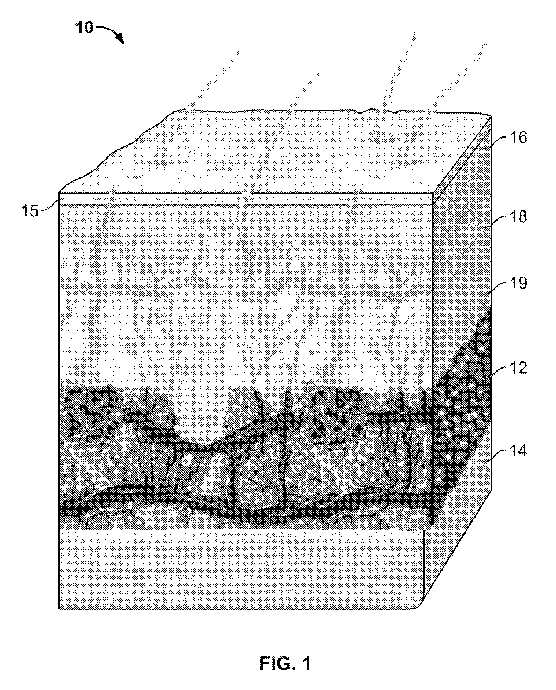
Treatment Limited to a Reticular Dermis Layer

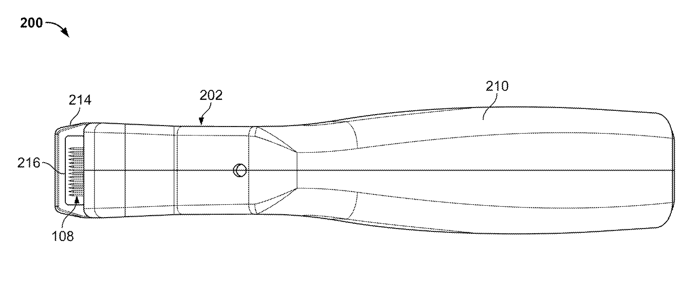
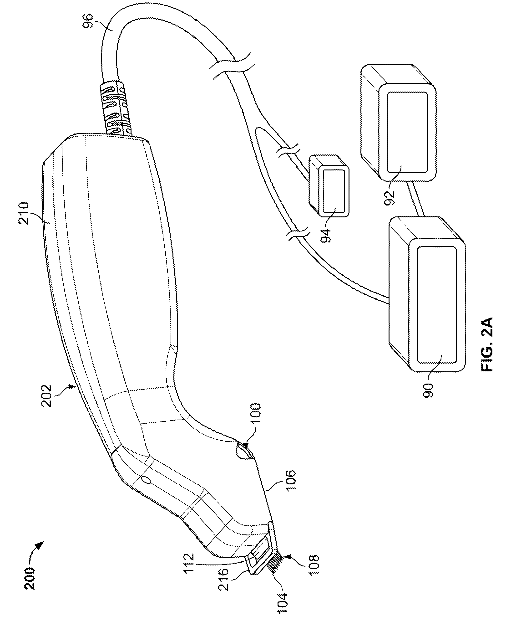
[0180]Patients were treated with a PID controlled bipolar RF electrode device (a frequency of 460 kHz) configured with 5 pairs of 30 gauge electrodes. The distance between two electrodes of a pair was about 1.25 mm, and the distance between two adjacent electrodes of an adjacent pair was about 2.5 mm. To protect the epidermis from RF heating at the insertion location, a proximal 3 mm of each electrode was insulated with a low-conductivity biocompatible material such as Teflon while the distal 3 mm were left exposed to function as the active portion. The treatment device body featured a smart electrode deployment system as described above. In such a system, the electrodes were configured to enter the epidermis at a 20° angle to the skin surface for a distance of 6 mm. Once inserted, each electrode pair transmitted a test current therebetween to sense the impedance of the tissue adjacent to the active portion of the electrodes. The test cur...


PUM


Abstract

The invention provides a system and method for percutaneous energy delivery in an effective, manner using one or more probes. Additional variations of the system include array of probes configured to minimize the energy required to produce the desired effect.

Description

CROSS-REFERENCE[0001]This application is a non-provisional of U.S. Provisional Application No. 61 / 080,386 filed Jul. 14, 2008 and a non-provisional of U.S. Provisional Application No. 61 / 099,671 filed Sep. 24, 2008.BACKGROUND OF THE INVENTION[0002]The systems and method discussed herein treat tissue in the human body. In a particular variation, systems and methods described below treat cosmetic conditions affecting, the skin of various body parts, including face, neck, and other areas traditionally prone to wrinkling, lines, sagging and other distortions of the skin.[0003]Exposure of the skin to environmental forces can, over time, cause the skin to sag, wrinkle, form lines, or develop other undesirable distortions. Even normal contraction of facial and neck muscles, e.g. by frowning or squinting, can also over time form furrows or bands in the face and neck region. These and other effects of the normal aging process can present an aesthetically unpleasing cosmetic appearance.[0004]...

Claims


Application Information

Patent Timeline
Patent Type & Authority Patents(United States)
IPC IPC(8): A61N7/02A61B18/14A61B18/22A61N5/067A61B18/12A61B18/20A61B18/18A61B18/00
CPCA61B2018/00452A61B18/1477A61B18/14A61B18/203A61B18/1206A61B2018/00011A61B2018/00994A61B18/20A61B2018/208A61N7/02A61B2018/00875A61B18/18A61B2018/1807A61B2018/1425A61B2018/143A61B2018/1475
Inventor MEHTA, BANKIM H.MCGILL, SCOTT A.
Owner SYNERON MEDICAL LTD
Why Eureka
Try Eureka