AOM modulation techniques employing transducers to modulate different axes

a transducer and axe technology, applied in the field of laser micromachining, can solve the problems of inability to achieve the effect of reducing the cost of workpieces, affecting the stability of laser pulses, and affecting the quality of workpieces, etc., to achieve the effect of facilitating the substantially full extinction of laser beams, preventing unwanted laser energy from impinging on workpieces, and facilitating laser pulse energy stability

Active Publication Date: 2005-12-08
ELECTRO SCI IND INC
View PDF13 Cites 36 Cited by
  • Summary
  • Abstract
  • Description
  • Claims
  • Application Information

AI Technical Summary

Benefits of technology

[0015] Certain embodiments and techniques described herein can achieve a variety of laser processing advantages over conventional laser systems and conventional laser machining methods. These embodiments and techniques include, but are not limited to, one or more of the following: digital control of frequency and/or amplitude AOM modulation techniques; intracavity and/or extracavity AOM modulation techniques including, but not limited to, frequency and/or amplitude modulation that facilitate substantially full ...

Problems solved by technology

In these laser operations, the workpiece may be expensive in terms of materials and/or prior processing.
If the laser output does not turn completely off, there is potential to “leak” or diffract energy to the workpiece in locations where damage to, change to, or effect on the material properties or characteristics is unacceptable.
In laser trimming, unwanted energy could, for example, induce undesirable electro-optical effects in the material that are undesirable.
Regardless of the laser operation, leaked laser energy has the pote...

Method used


Image

  • AOM modulation techniques employing transducers to modulate different axes
  • AOM modulation techniques employing transducers to modulate different axes
  • AOM modulation techniques employing transducers to modulate different axes

Examples


Embodiment Construction

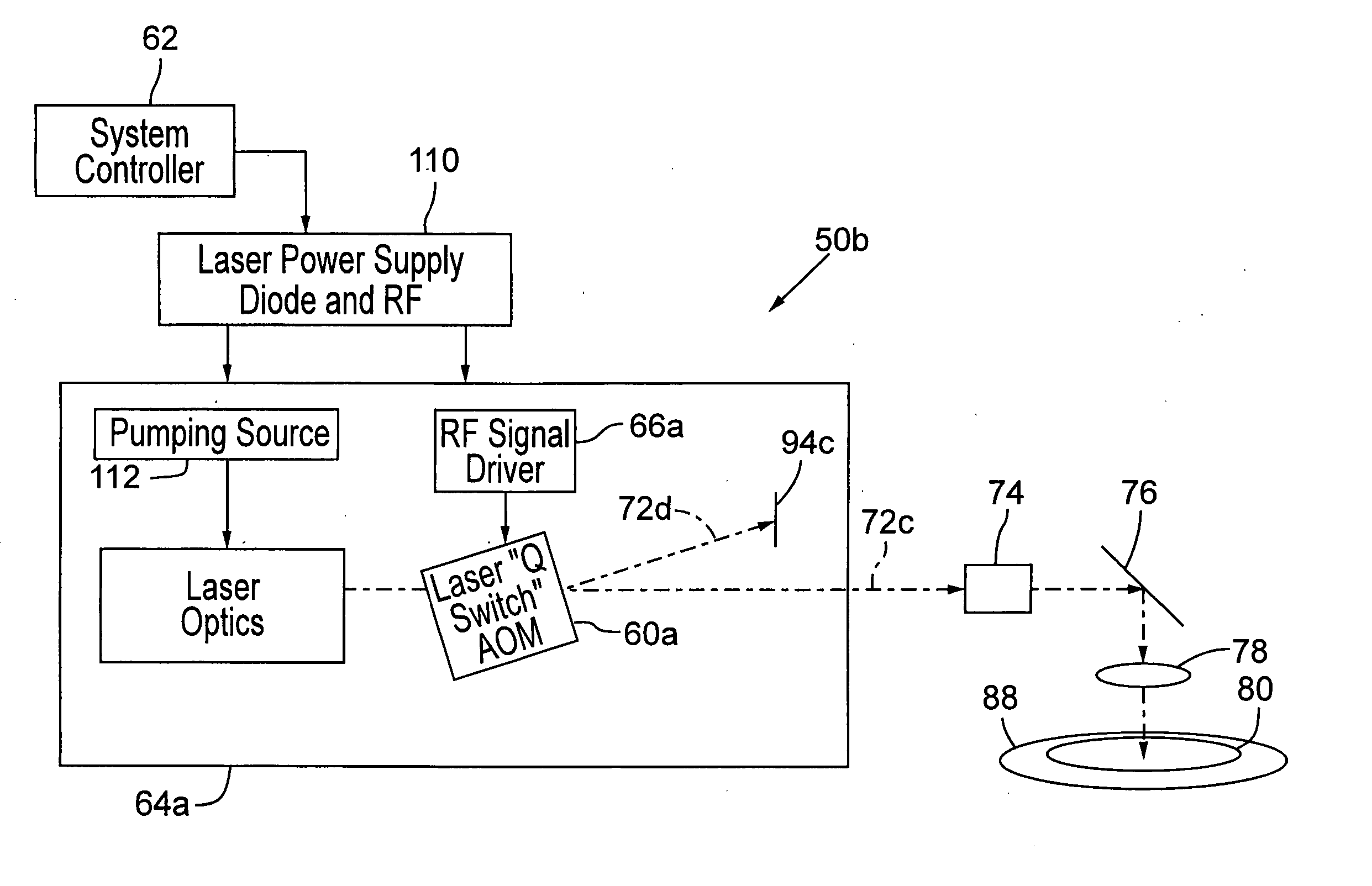
[0058]FIG. 6 shows an embodiment of a laser system 50 that employs a modulation-enhanced AOM 60 as a pulse gating device, the AOM 60 having a beam entrance surface 52 and a beam exit surface 54. With reference to FIG. 6, a laser system controller 62 provides control signals directly or indirectly to a laser 64 and an RF driver 66 that directly or indirectly controls the performance of the AOM 60 as described later in more detail. The laser 64 emits a laser beam that is propagated along an optical path 72 that may contain a variety of optical components 74, such as beam-expanding optics, or a variety of turn mirrors (not shown) before the laser beam enters the AOM 60 that propagates zero- and / or first-order beams 16 and 18. The laser beam is preferably a Q-switched or pulsed laser beam for most applications, but may be a continuous-wave (CW) beam for some applications.

[0059] Typically, one of the zero-order beams 16 or first-order beams 18 is subsequently directed by one or more tur...


PUM

PropertyMeasurementUnit
Angleaaaaaaaaaa
Efficiencyaaaaaaaaaa
Frequencyaaaaaaaaaa

Abstract

Digital control of frequency and/or amplitude modulation techniques of an intracavity and/or extracavity AOM (60) facilitate substantially full extinction of a laser beam (90) to prevent unwanted laser energy from impinging a workpiece (80); facilitate laser pulse amplitude stability through closed-loop control of pulse-to-pulse laser energy; facilitate beam-positioning control including, but not limited to, closed-loop control for applications such as alignment error correction, beam walk rectification, or tertiary positioning; and facilitate employment of more than one transducer on an AOM (60) to perform any of the above-listed applications.

Description

RELATED APPLICATION [0001] This patent application claims benefit of U.S. Provisional Application No. 60 / 577,796, filed Jun. 7, 2004.COPYRIGHT NOTICE [0002]© 2005 Electro Scientific Industries, Inc. A portion of the disclosure of this patent document contains material that is subject to copyright protection. The copyright owner has no objection to the facsimile reproduction by anyone of the patent document or the patent disclosure, as it appears in the Patent and Trademark Office patent file or records, but otherwise reserves all copyright rights whatsoever. 37 CFR § 1.71 (d). TECHNICAL FIELD [0003] The present invention relates to laser micromachining and, in particular, to methods and systems employing AOM frequency and / or amplitude modulation to improve laser machining performance. BACKGROUND OF THE INVENTION [0004]FIG. 1 is a schematic diagram of a typical prior art laser 2 employing a traditional acousto-optic Q-switch 10a. FIGS. 2A and 2B (generically, FIG. 2) are alternative ...

Claims


Application Information

Patent Timeline
IPC IPC(8): G01N23/04B23K26/08G02F1/33G02F1/29G02F1/01B23K1/00H01S3/00H01S3/11B23K26/06
CPCB23K26/0626B23K26/0648B23K26/0665G02F1/0121G02F1/292G02F1/33G02F1/332G02F2201/16H01S3/005H01S3/1068H01S3/117H01S3/1306H01S3/136B23K26/064B23K26/082B23K26/0622
Inventor JOHNSON, JAY
Owner ELECTRO SCI IND INC
Why Eureka
Try Eureka