Thermally switched optical filter incorporating a refractive optical structure

a technology of optical filter and refractive optical structure, which is applied in the direction of static indicating devices, instruments, non-linear optics, etc., can solve the problems of limited switching speed and cycle lifetime, and the amount of light transmitted through the device may therefore change as well, so as to achieve privacy, glare or solar heat gain, the effect of partial aesthetics

Inactive Publication Date: 2011-02-03
RAVENBRICK
View PDF102 Cites 33 Cited by
  • Summary
  • Abstract
  • Description
  • Claims
  • Application Information

AI Technical Summary

Benefits of technology

[0017]This technology may employ both specular and diffusive optical effects as described above, to create windows or window filters that exhibit both transparent and opaque privacy-type modes, and prevent the concentration of reflected solar energy in UV, visible, or IR bands in...

Problems solved by technology

These switchable mirrors, which are chemically related to rechargeable batteries, may rely on the physical migration of ions across a barrier under the influence of an electric field and, therefore, have limited switching speeds and cycle lifetimes. In addition, electrically operated “light valves” that combine liquid crystals...

Method used


Image

  • Thermally switched optical filter incorporating a refractive optical structure
  • Thermally switched optical filter incorporating a refractive optical structure
  • Thermally switched optical filter incorporating a refractive optical structure

Examples


Embodiment Construction

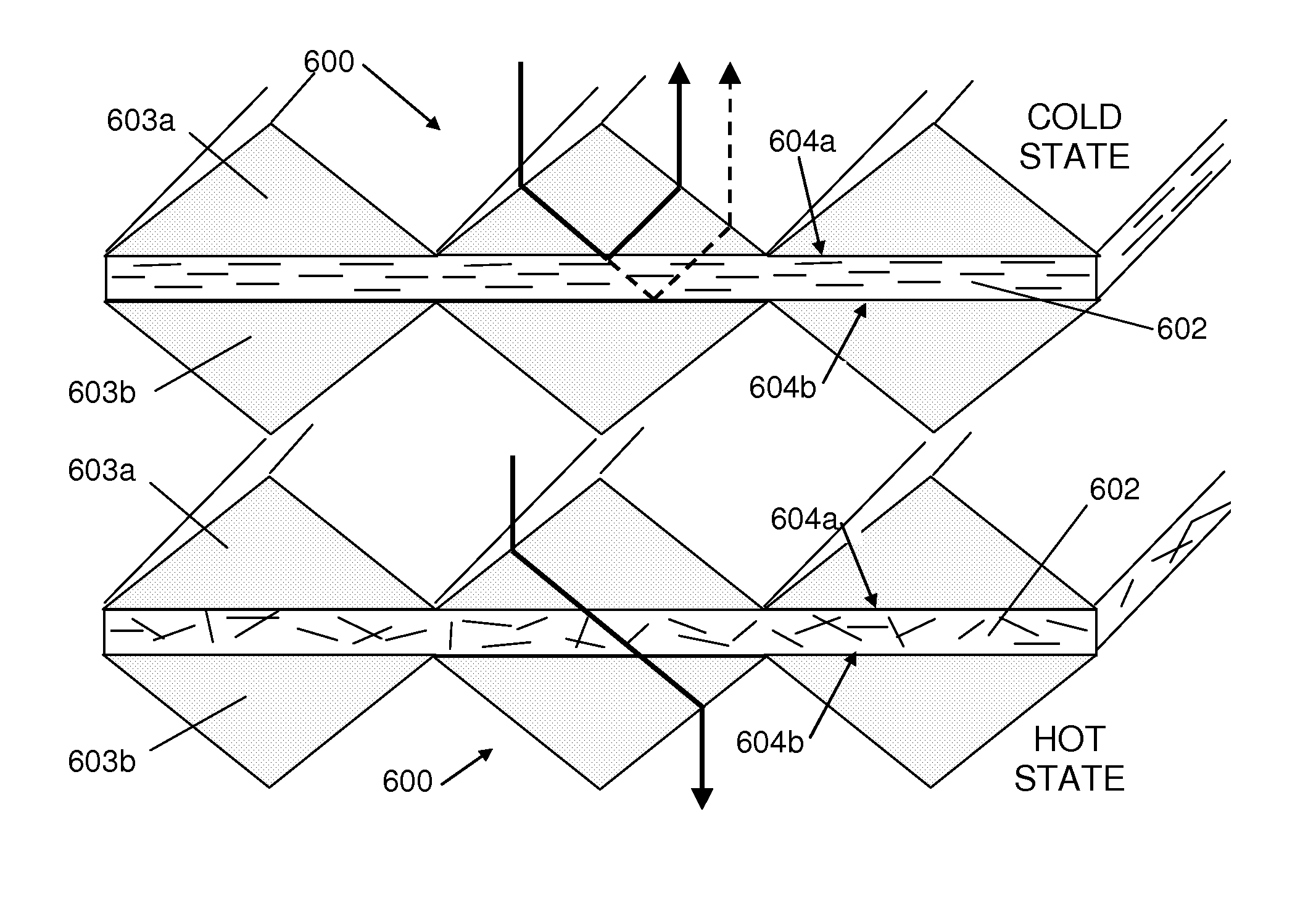
[0026]For the purposes of this specification, the term “thermoreflective” shall refer to any object, device, or material having a reflectivity that varies as a function of temperature. Similarly, “thermoabsorptive” and “thermoflourescent” shall refer to any objects, devices, or materials having an absoptivity or fluorescence, respectively, that varies as a function of temperature. Since light transmission is a function of reflection, absorption, and re-radiation of light, any of these objects, devices, or materials may also be properly described by the more generic term, “thermochromic”.

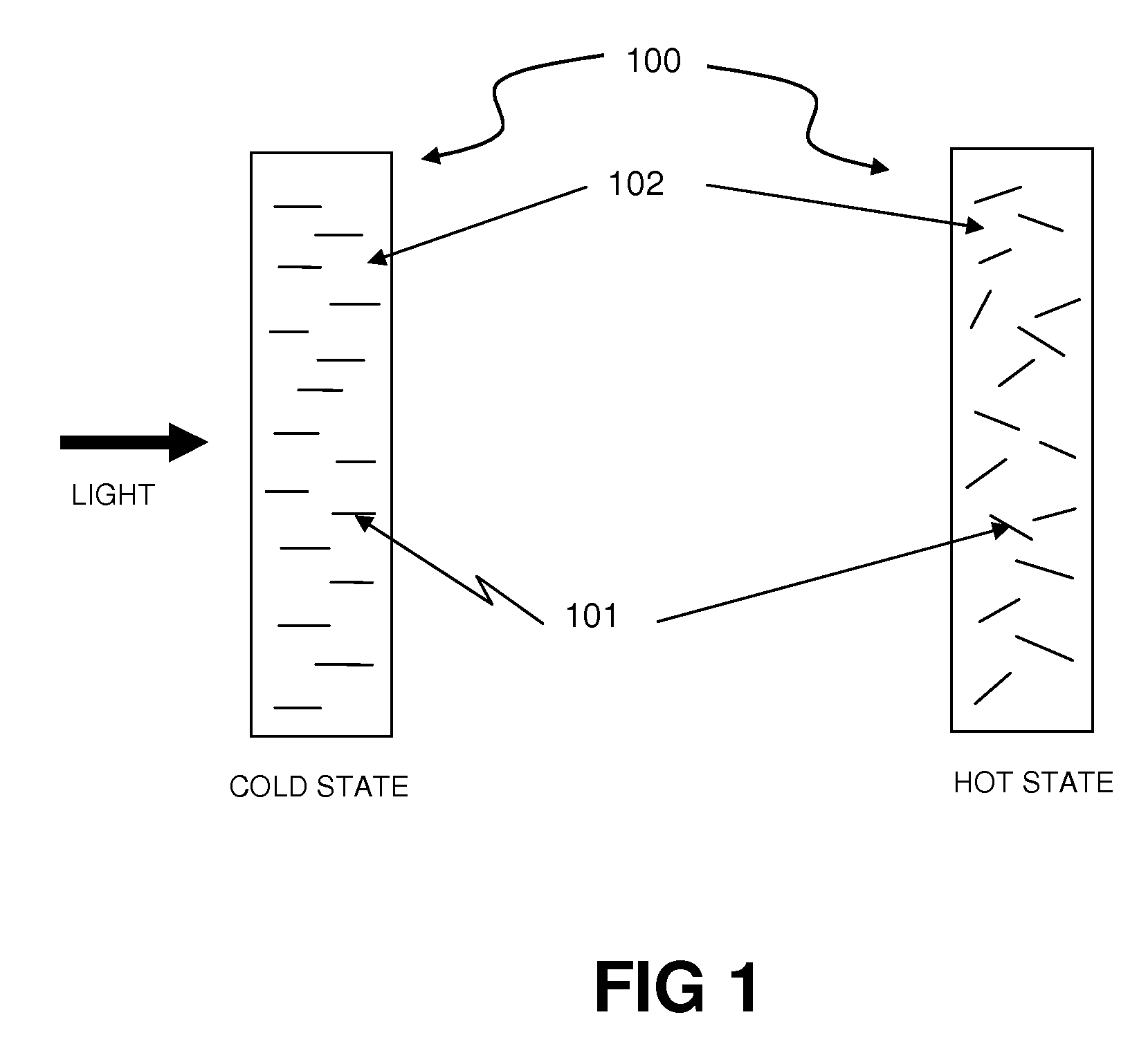
[0027]FIG. 1 is a schematic, cross-section view of an exemplary form of a thermochromic filter device 100. The filter device 100 may be composed of included “orientation dependent colorant” or ODC materials 101 inside a transmissive, thermotropic, order-providing carrier material 102. At a lower temperature, assuming that the ODC molecules interact more strongly with incoming light perpendicular to t...


PUM


Abstract

A thermochromic, thermotropic, or thermoreflective filter relies on a mismatch between the index of refraction of a thermotropic material (e.g., a liquid crystal) and a substrate material that includes refractive or diffractive features. At colder operating temperatures, the refraction mismatches are eliminated or minimized such that the filter becomes transparent, whereas at high operating temperatures the refraction mismatches are increased such that for light at appropriate incidence angles, the structure becomes highly reflective. This filter has particular but not exclusive application as a temperature-controlled “smart mirror” for use in windows, walls, roofing, and other building materials.

Description

CROSS REFERENCE TO RELATED APPLICATIONS[0001]This application claims the benefit of priority pursuant to 35 U.S.C. §119(e) U.S. provisional patent application No. 61 / 262,024 entitled “Thermally switched optical filter” filed 17 Nov. 2009; U.S. provisional patent application No. 61 / 296,127 entitled “Thermally switched optical filter incorporating a guest-host architecture” filed 19 Jan. 2010; and U.S. provisional patent application No. 61 / 299,505 entitled “Thermally switched optical filter incorporating a guest-host architecture” filed 29 Jan. 2010, the disclosures of which are hereby incorporated herein by reference in their entirety. This application is also a continuation-in-part of U.S. patent application Ser. No. 12 / 758,573 entitled “Thermally switched optical filter incorporating a guest-host architecture” filed 12 Apr. 2010, which further claims the benefit of priority pursuant to 35 U.S.C. §119(e) of the following: U.S. provisional patent application No. 61 / 168,513 entitled “...

Claims


Application Information

Patent Timeline
IPC IPC(8): G02F1/1335G02F1/01G02F1/19
CPCG02F1/19G02F1/132
Inventor MCCARTHY, WILPOWERS, RICHARD M.
Owner RAVENBRICK
Why Eureka
Try Eureka