Solar cell module

a solar cell and module technology, applied in the field of solar cell modules, can solve the problem of solar cell cracks easily caused, and achieve the effect of improving the production yield of solar cells

Inactive Publication Date: 2008-11-13
PANASONIC INTELLECTUAL PROPERTY MANAGEMENT CO LTD
View PDF3 Cites 53 Cited by
  • Summary
  • Abstract
  • Description
  • Claims
  • Application Information

AI Technical Summary

Benefits of technology

[0012]The present invention has been made in view of the foregoing problem. Accordingly, an object of the present invention is to provide a solar

Problems solved by technology

Consequently, there arises a problem that

Method used


Image

  • Solar cell module
  • Solar cell module
  • Solar cell module

Examples


first embodiment

(Schematic Configuration of a Solar Cell Module)

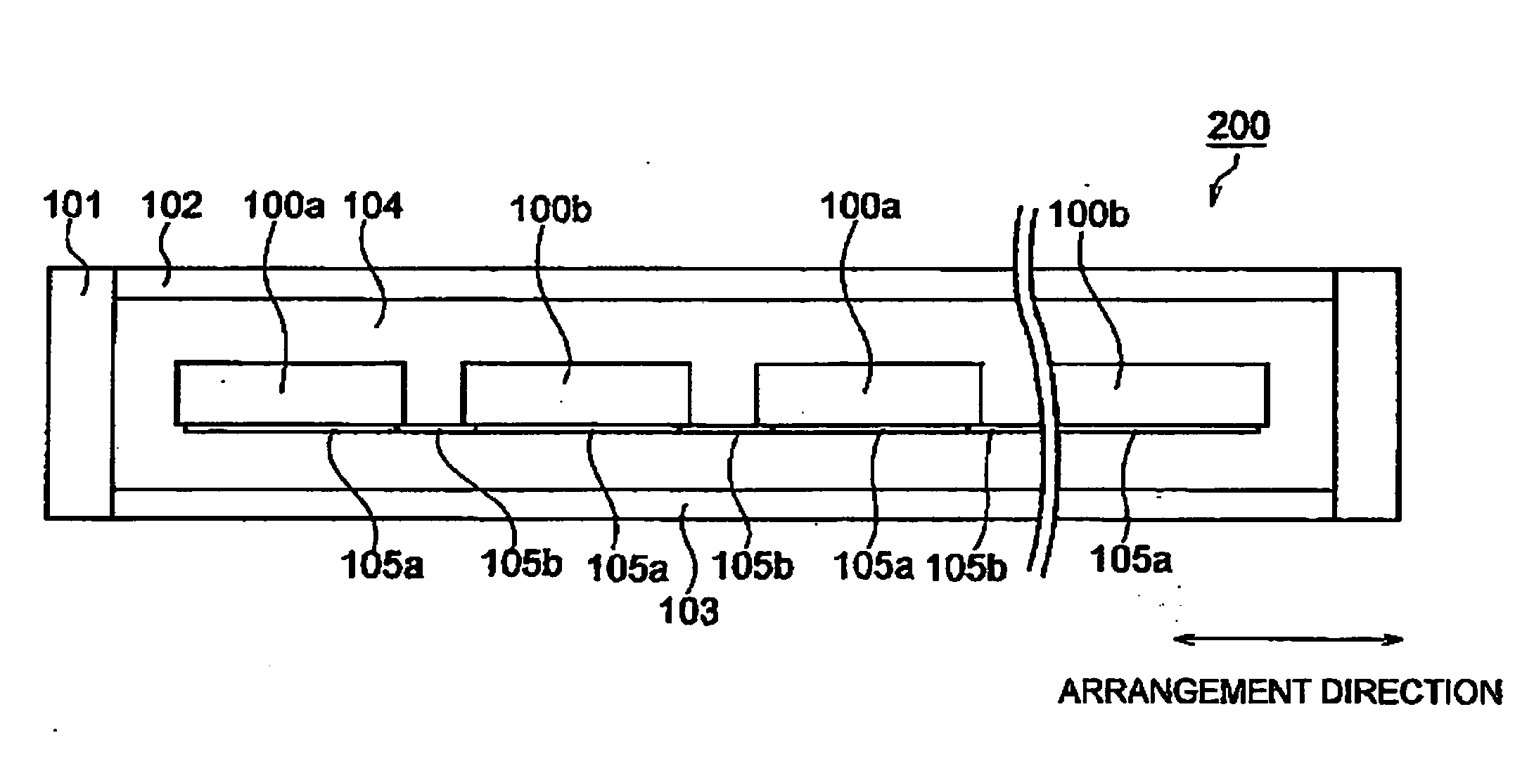
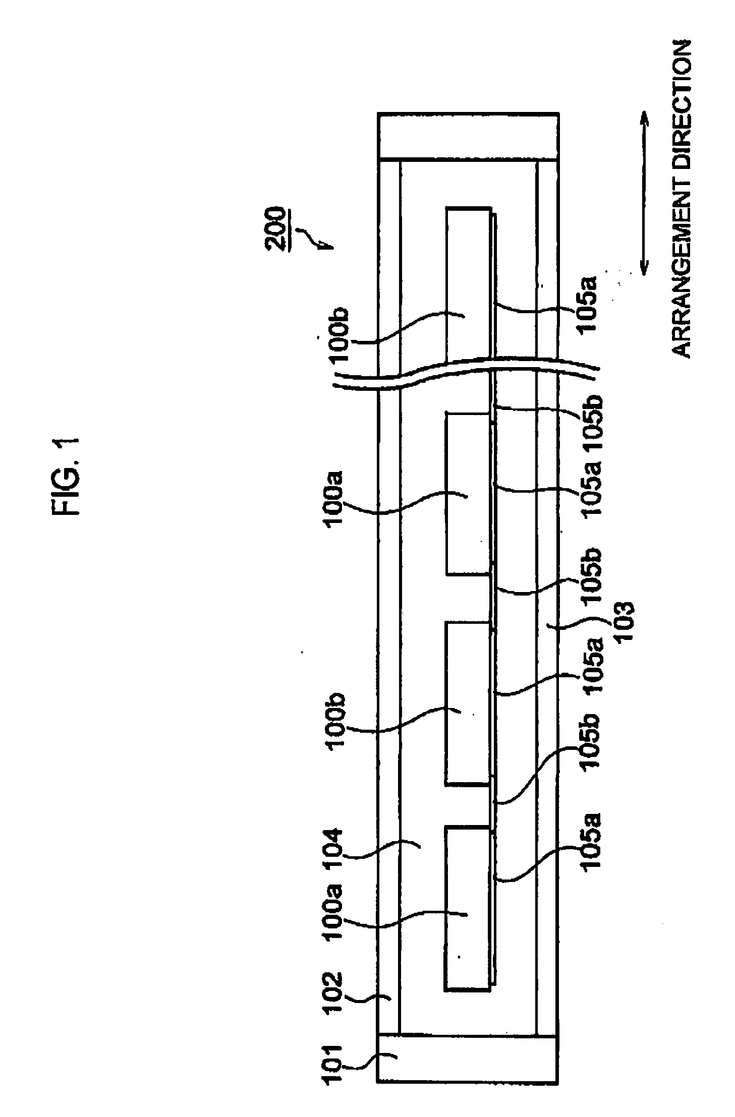
[0031]A schematic configuration of a solar cell module according to a first embodiment of the present invention will be described below by referring to FIG. 1. FIG. 1 is a view showing the configuration of a solar cell module 200 according to the first embodiment of the present invention.

[0032]As shown in FIG. 1, the solar cell module 200 has multiple solar cells 100, a light-receiving surface side protection member 102, a back surface side protection member 103, and a sealing member 104. In addition, the solar cell module 200 has a wiring member 105 by which the solar cells adjacent to each other are connected in series. Furthermore, a frame body may be provided in an outer circumference of the solar cell module 200.

[0033]The solar cell 100 has a light-receiving surface receiving sunlight and a back surface provided on the opposite side of the light-receiving surface. The multiple solar cells 100 are arranged in an arrangement directi...

second embodiment

[0085]The configuration of a solar cell module according to a second embodiment of the present invention will be described below.

[0086]The solar cell module according to the present embodiment has a similar schematic configuration to that of the solar cell module 200 shown in FIG. 1.

[0087]The solar cell module according to the present embodiment includes multiple solar cells 100 which are arranged in an arrangement direction.

[0088]FIG. 8 is a backview showing a state where third and fourth solar cells 100c and 100d are connected on a back surface. In the solar cell module according to the present embodiment, the third and fourth solar cells 100c and 100d are alternately arranged to be adjacent to each other in the arrangement direction.

[0089]Photoelectric converters of the third and fourth solar cells 100c and 100d may be manufactured by using semiconductor substrates having the same polarity, or semiconductor substrates having opposite polarities.

[0090]FIG. 9 is a cross-sectional v...


PUM


Abstract

The first and second solar cells are arranged to be adjacent to each other in the arrangement direction. On the back surface of the first solar cell, the multiple first n-type regions are formed in the arrangement direction and the multiple first p-type regions are formed between each of the multiple first n-type regions. On the back surface of the second solar cell, the multiple second p-type regions are formed in the arrangement direction and the multiple second n-type regions are formed between each of the multiple second p-type regions. Each of the multiple first n-type regions and each of the multiple second p-type regions are formed on the back surface in a substantially straight line. Each of the multiple first p-type regions and each of the multiple second n-type regions are formed on the back surface in a substantially straight line.

Description

CROSS REFERENCE TO RELATED APPLICATIONS[0001]This application is based upon and claims the benefit of priority from the prior Japanese Patent Application No. P 2007-124729, filed on May 9, 2007; the entire contents of which are incorporated herein by reference.BACKGROUND OF THE INVENTION[0002]1. Field of the Invention[0003]The present invention relates to a solar cell module in which solar cells are electrically connected on the back surfaces thereof.[0004]2. Description of the Related Art[0005]Solar cells directly convert clean and unlimitedly-supplied sunlight into electricity, and thus are expected as one of new energy sources.[0006]Energy output per solar cell is approximately a several W. Accordingly, when solar cells are used as a power source for houses, buildings or the like, a solar cell module having multiple solar cells connected in series or parallel is used.[0007]Here, there has been known a back-contact-type solar cell. This type of solar cell has a light-receiving sur...

Claims


Application Information

Patent Timeline
IPC IPC(8): H01L31/042H01L31/06H01L31/0224H01L31/05
CPCH01L31/022425H01L31/068Y02E10/547H01L31/02245H01L31/0516H01L31/0747
Inventor KINOSHITA, TOSHIHIROMARUYAMA, EIJIHISHIDA, YUJI
Owner PANASONIC INTELLECTUAL PROPERTY MANAGEMENT CO LTD
Why Eureka
Try Eureka