

Process for producing acetic acid
a technology of acetic acid and process, which is applied in the preparation of carboxylic compounds, separation processes, organic chemistry, etc., can solve the problems of insufficient hydrogen iodide removal efficiency, insufficient overhead separation, and inability to efficiently separate overhead, so as to achieve high-quality acetic acid, prevent contamination of impurities, and operate stably and continuously
- Summary
- Abstract
- Description
- Claims
- Application Information
AI Technical Summary
Benefits of technology
Problems solved by technology
Method used
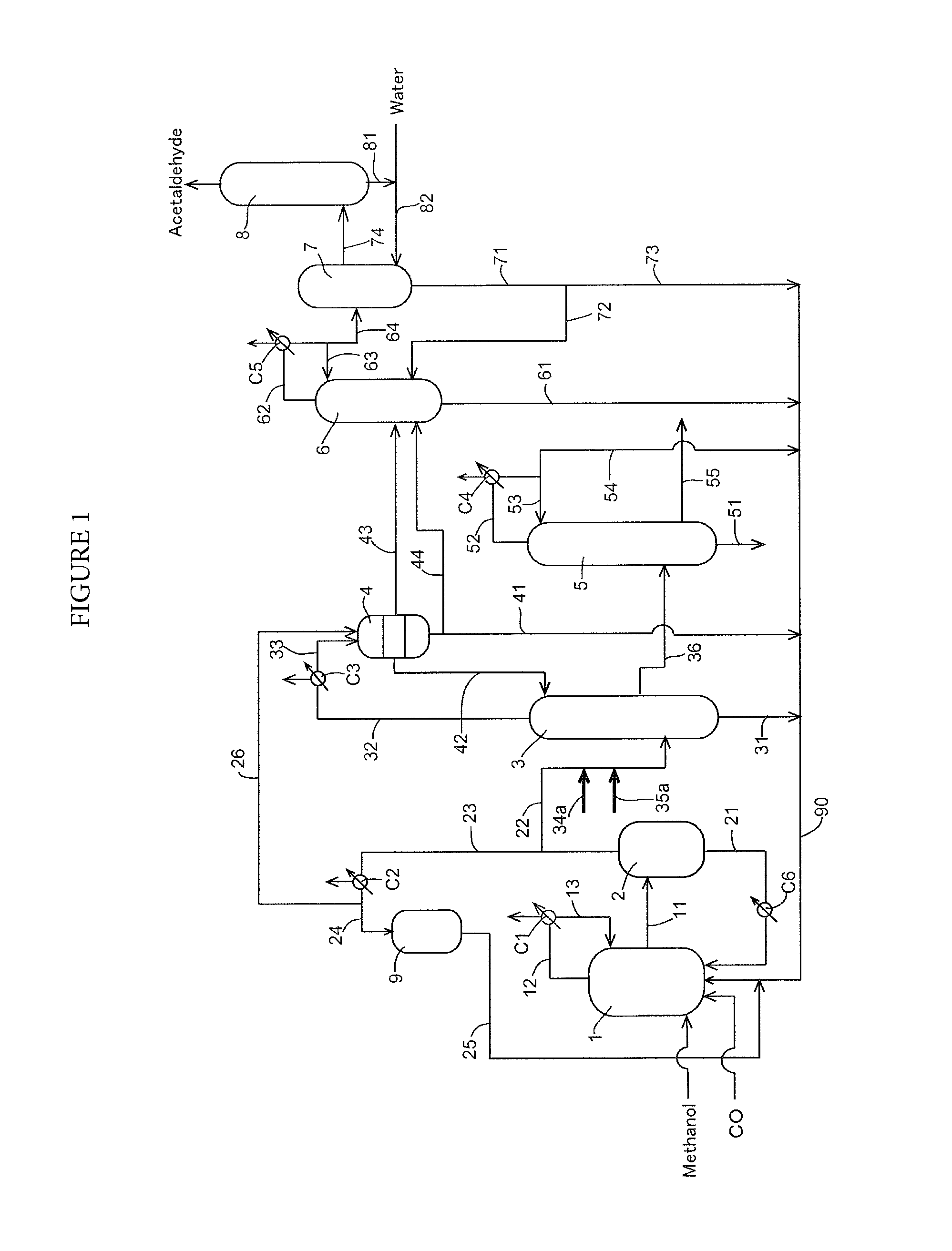
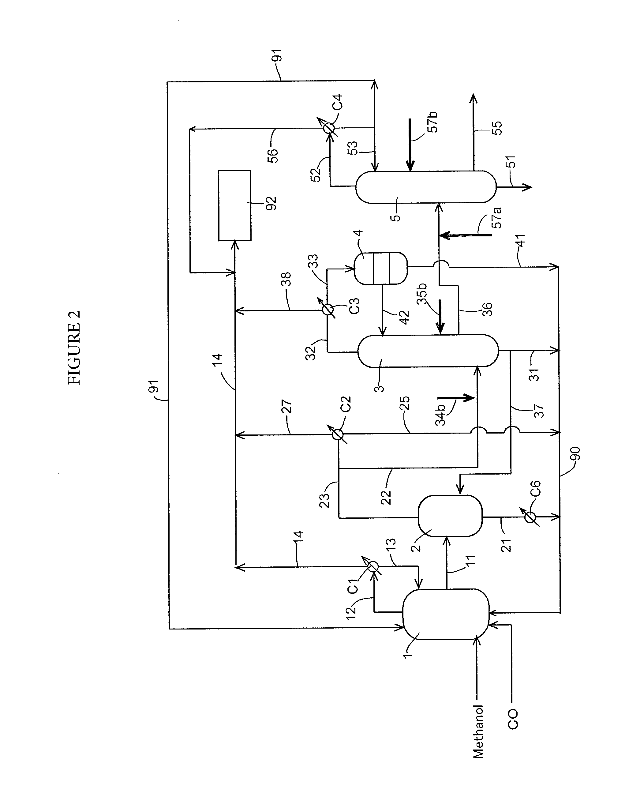
Image


Examples
examples 1 to 4
[0140]The corrosion test was carried out in the same manner as in Comparative Example 1 except that the charging mixture (volatile phase component) having appropriate methyl acetate and water concentrations in each Example is fed to the first distillation column and that the reflux ratio in the first distillation column and the amounts of the light phase and the heavy phase recycled to the reaction system were changed depending on the methyl acetate and water concentrations.
[0141]Operation conditions in each of Examples and Comparative Examples are shown in Table 1. The results of the corrosion test are shown in Table 2. The unit of numerical values in Table 2 is the corrosion rate “mm / Y”.
[0142]
TABLE 1Parts byweightComparative ExamplesExamples(ppm for HI)1231234FeedFlow rate100100100100100100100MeI38.238.5383838.53736MA0.30.3100.514.27.2Water6.544441.22HI5000500020040002000600300AC54.556.747.657.156.357.454.7Side-Flow rate5455.243.555.255.254.251.6cutMeI2.92.62.31.74.03.12.3MA0.030....
PUM
| Property | Measurement | Unit |
|---|---|---|
| partial pressure | aaaaa | aaaaa |
| partial pressure | aaaaa | aaaaa |
| absolute pressure | aaaaa | aaaaa |
Abstract
Description
Claims
Application Information