Recording medium, reporduction apparatus, recording method, integrated circuit, program and reporduction method

a technology of reporduction apparatus and recording medium, which is applied in the field of recording medium, can solve the problems of concentrated decoding load and enormous amount of decoding load at reproduction, and achieve the effect of maintaining a degree of flexibility in the design of the apparatus and facilitating the manufacture of the apparatus at low cos

Active Publication Date: 2006-07-13
PANASONIC CORP
View PDF13 Cites 56 Cited by
  • Summary
  • Abstract
  • Description
  • Claims
  • Application Information

AI Technical Summary

Benefits of technology

[0005] The object of the present invention is to provide a recording medium that realizes high definition level of graphics display, as well as avoiding rise in production cost.
[0010] By defining such a buffering period, it becomes possible to avoid concentration of an enormous amount of decoding load to one point. In addition, if the use of the hardware resource for decoding simultaneously contends other processing, buffering period can be provided so as to relocate the graphics decoding period, thereby avoiding such contention.
[0013] According to this construction, a memory management start is indicated by a decode time stamp of a packet storing control information. Therefore, by referring to the decode time stamp, it becomes possible to know on which point of the reproduction timeline each buffer for the decoder model should be flashed. If the flash point is considered as a starting point of memory management, it is easy to grasp the chronological occupancy transition of the buffer that stores control information, the buffer that stores graphics before being decoded, and the buffer that stores graphics after being decoded. By changing the value of this decode time stamp, it is possible to adjust the chronological transition of the state of the buffers. According to such adjustment, it becomes possible to avoid buffer overflow at the reproduction apparatus. Therefore, it becomes easy to implement hardware / software at the development stage of reproduction apparatus.
[0018] The presentation time stamp of a packet storing graphics indicates a decoding ending time, and the presentation time stamp of a packet storing control information indicates a time obtained by adding a predetermined period to the decoding ending time. Therefore only by referring to the presentation time stamps, the controller can perform updating at an adequate timing without receiving from the processor any decoding-completion notification of graphics data. If such update is performed, it becomes possible to assure update synchronized with the display rate of the moving picture, regardless of the manner of implementation in the reproduction apparatus.
[0019] Since closer processor-controller connection is realized regardless of the manner of processor-controller implementation in the reproduction apparatus, it becomes possible to maintain a degree of flexibility in the apparatus designing, as well as facilitating manufacturing apparatuses at low cost.

Problems solved by technology

However, realization of such a high definition incurs an enormous amount of decoding load at reproduction.
When this is applied, an enormous amount of decoding load will be concentrated in the reproduction apparatus at points immediately before display.

Method used


Image

  • Recording medium, reporduction apparatus, recording method, integrated circuit, program and reporduction method
  • Recording medium, reporduction apparatus, recording method, integrated circuit, program and reporduction method
  • Recording medium, reporduction apparatus, recording method, integrated circuit, program and reporduction method

Examples


first embodiment

[0108] A First Embodiment of a recording medium according to the present invention is explained below.

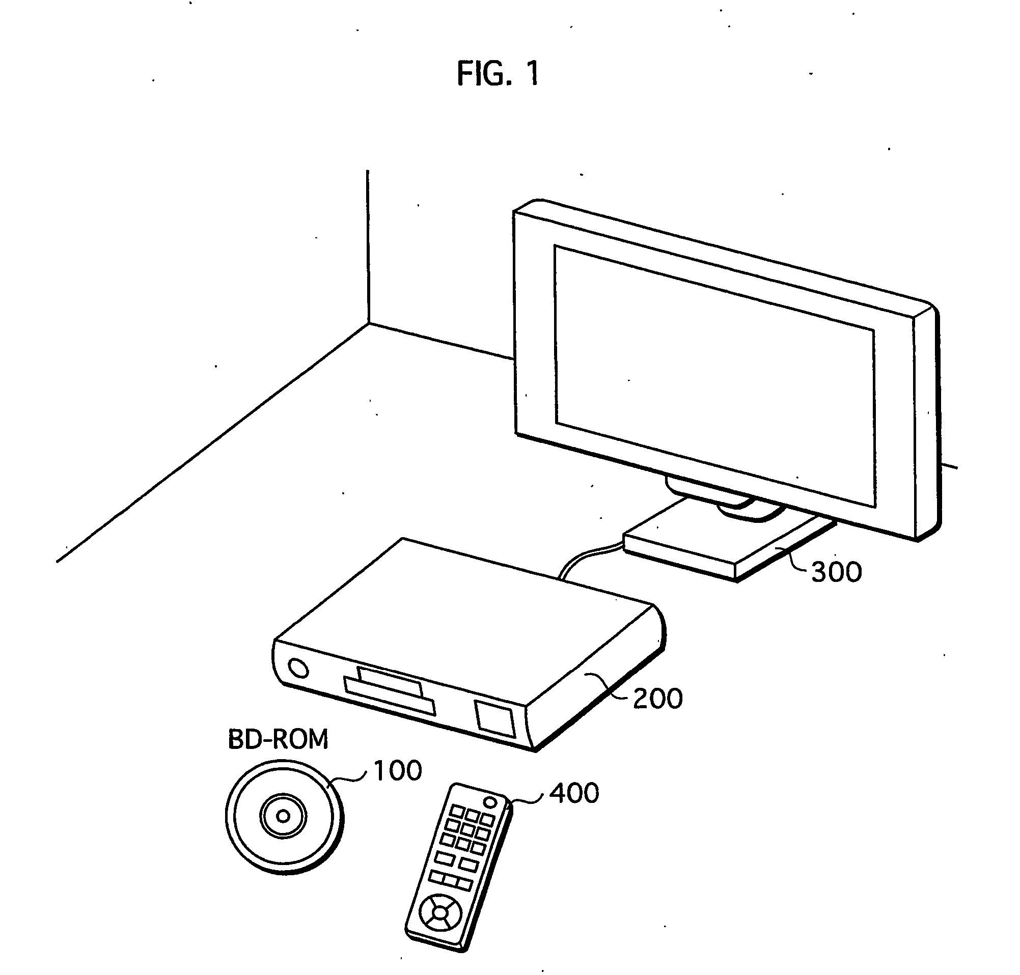
[0109]FIG. 1 illustrates an example of use of the recording medium. In the drawing, BD-ROM 100 is the recording medium according to the present invention. The BD-ROM 100 is used for providing data of movie works to a Home Theatre System structured by a reproduction apparatus 200, a television 300, and a remote controller 400.

[0110] The recording medium according to the present invention is manufactured by an improvement in an application layer of a BD-ROM. FIG. 2 illustrates a structure of the BD-ROM.

[0111] In the drawing, the BD-ROM is shown at a bottom of the drawing, and a track on the BD-ROM is shown above the BD-ROM. The track is actually in a spiral shape on the disk, but shown in a line in the drawing. The track includes a lead-in area, a volume area, and a lead-out area. The volume area in this drawing has a physical layer, a file system layer, and an application layer. A...

second embodiment

[0349] The First Embodiment explained above is for graphics dedicated for subtitle display. On the contrary, a Second Embodiment is on graphics for interactive display.

[0350] Among the embodiments of a recording medium according to the present invention, an example of use of the recording medium is explained as follows. Just as in the First Embodiment, the recording medium of the Second Embodiment can also be manufactured by an improvement in an application layer of a BD-ROM. FIG. 41 is a diagram schematically illustrating a structure of the AVClip of the second embodiment.

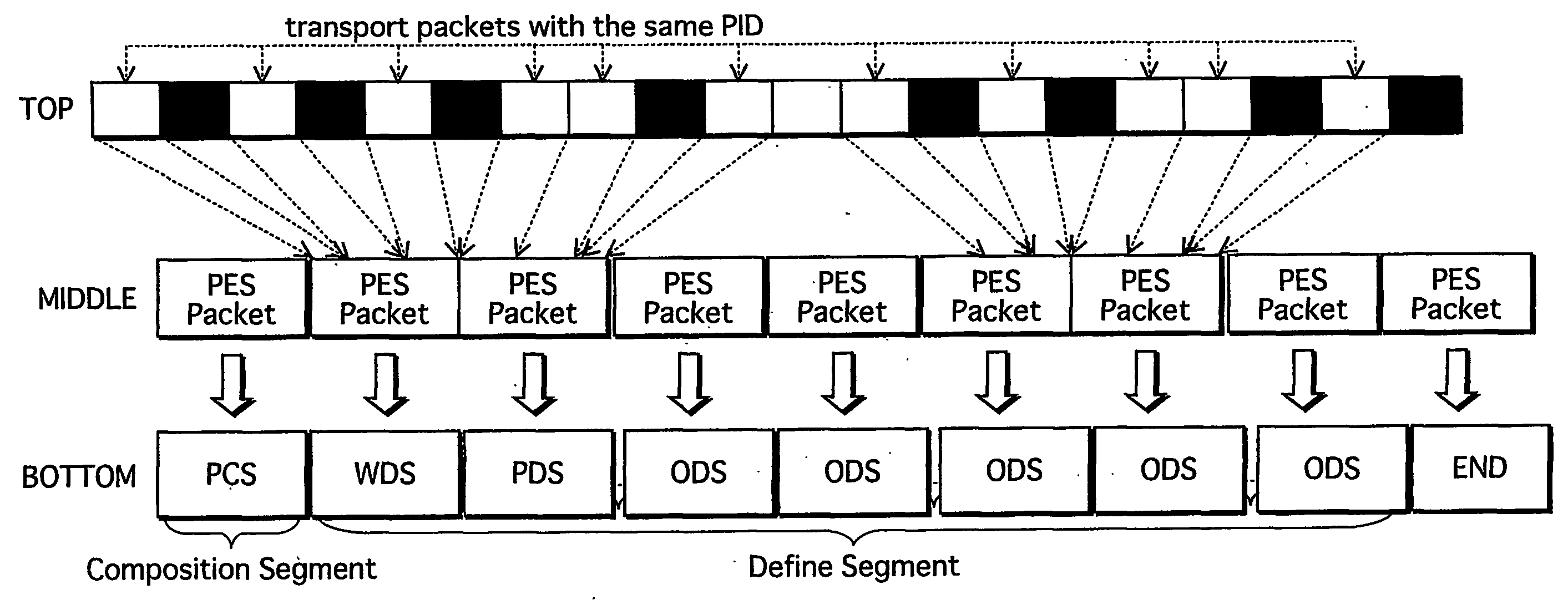
[0351] The AVClip (shown in the middle) is structured in a following manner. The video stream made of plural video frames (picture pj1, pj2, and pj3), and the audio stream made of plural audio frames (top row of the drawing) are respectively converted into a line of PES packets (second row of the drawing), and then into a line of TS packets (third row of the drawing). The interactive graphics stream (bottom row ...

third embodiment

[0507] The present embodiment relates to a manufacturing method of a BD-ROM. FIG. 79 illustrates a method of manufacturing the PCS explained in the first embodiment.

[0508] The manufacturing method of a BD-ROM includes: a material producing step S201 of photographing an image picture, and of recording corresponding audio, for example; an authoring step S202 of generating an application format; and a press step S203 of completing the BD-ROM by performing pressing / lamination.

[0509] Among these steps, the authoring step directed to BD-ROM includes the following step S204-Step S210.

[0510] At Step S204, control information, window define information, palette define information, and graphics are described. At Step S205, the control information, the window define information, the palette define information, and the graphics are respectively converted into a functional segment. At Step S206, PTS in PCS is set, according to when the picture to be displayed in sync appears. At Step S207, DT...


PUM

PropertyMeasurementUnit
timeaaaaaaaaaa
timeaaaaaaaaaa
timeaaaaaaaaaa

Abstract

AVClip recorded in BD-ROM is obtained by multiplexing a graphics stream and a video stream. The graphics stream is a PES packet sequence that includes 1) PES packets storing graphics data (ODS) and 2) PES packets storing control information (PCS). In each ODS, values of DTS and PTS indicate a timing of decoding start for corresponding graphics data, and a timing of decoding end for corresponding graphics data, respectively. In each PCS, a value of PTS indicates a display timing of corresponding decoded graphics data combined with the video stream.

Description

TECHNICAL FIELD [0001] The present invention relates to a recording medium such as BD-ROM, and to a reproduction apparatus. The present invention particularly relates to a technology for realizing subtitle display and interactive display, by means of graphics. BACKGROUND ART [0002] Subtitle display by means of graphics has an important mission of conveying words uttered by the characters in a work, to people in every area of the world. One conventional technology for realizing subtitle display is the subtitle application of ETSI EN 300 743 standard (ETSI: European Telecommunication Standards Institute). The subtitle application is a video stream to be reproduced together with subtitle display by means of graphics. Here, the graphics that correspond to subtitle are displayed as a data stream of MPEG2 standard. The data stream is a sequence of PES packets, where each PES packet has a PTS (presentation time stamp). ETSI EN 300 743 standard defines the timing of subtitle display in a su...

Claims


Application Information

Patent Timeline
Patent Type & Authority Applications(United States)
IPC IPC(8): H04N5/91G11B27/10G11B27/30H04N5/85H04N5/92H04N9/82
CPCG11B27/10G11B27/105G11B27/3027G11B27/3036H04N9/8227H04N5/783H04N5/85H04N9/8042H04N9/8205G11B2220/2541G11B20/10H04N5/92H04N5/84
Inventor MCCROSSAN, JOSEPHOKADA, TOMOYUKIMOCHINAGA, KAZUHIRO
Owner PANASONIC CORP
Why Eureka
Try Eureka