Mirror driving device and method of controlling the device

一种驱动设备、驱动电压的技术,应用在光学、仪器、电气元件等方向,能够解决影响、结构扰动、谐振频率低等问题,达到谐振频率高、快速响应、干扰振动的影响抑制的效果

Active Publication Date: 2013-08-14
FUJIFILM CORP
View PDF5 Cites 27 Cited by
  • Summary
  • Abstract
  • Description
  • Claims
  • Application Information

AI Technical Summary

Problems solved by technology

[0015] ●Because many cantilevers are folded for sufficient displacement, the resonant frequency is low and the structure is susceptible to perturbations
[0016] ●Because the center of the mirror does not match the center of the device, approximately double the space is required when installing MEMS so that the center of the mirror is placed inside a cylindrical tube such as an endoscope

Method used


Image

  • Mirror driving device and method of controlling the device
  • Mirror driving device and method of controlling the device
  • Mirror driving device and method of controlling the device

Examples


no. 1 example

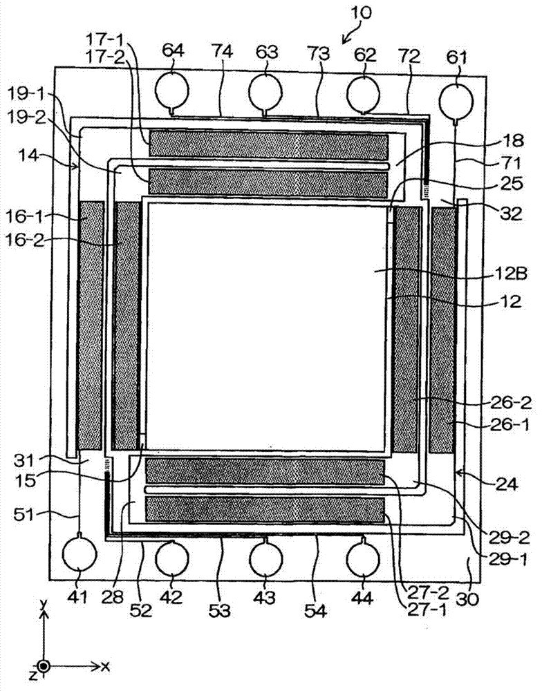
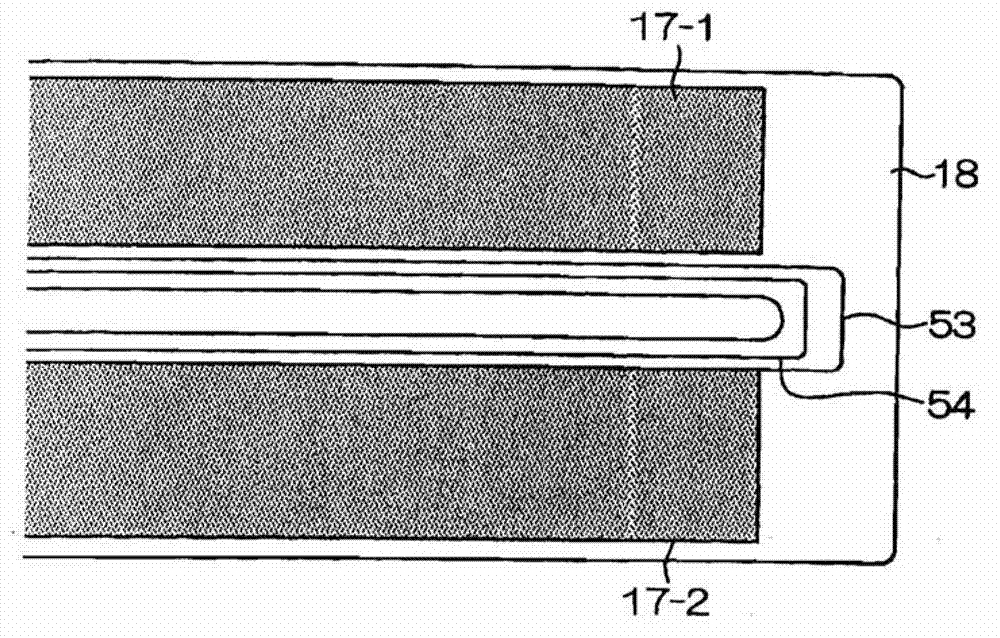
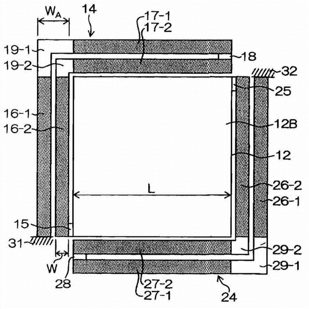
[0058] figure 1 is a plan view of the MEMS scanner device according to the first embodiment. figure 2 yes figure 1 A partially enlarged view of . image 3 is schematically depicted figure 1 A diagram of the device structure. As depicted in these figures, a MEMS scanner device 10 (corresponding to a "mirror drive device") according to the present embodiment includes: a mirror part 12; two actuators 14 and 24 surrounding this mirror part 12; and a support The frame 30 of these actuators 14 and 24 is fixed. At diagonal positions of the mirror member 12, mirror support members 15 and 25 are formed. The actuators 14 and 24 have one end connected to the mirror support members 15 and 25 and the other end fixed to a fixed part, the fixed parts being denoted by reference numerals 31 and 32, respectively.

[0059] The mirror member 12 in this example has a substantially rectangular shape in plan view. On the mirror surface (upper surface of mirror member 12 ) serving as refle...

no. 2 example

[0151] Figure 19 is a schematic diagram of the structure of the MEMS scanner device according to the second embodiment. exist Figure 19 in, give Figure 1 to Figure 3 The same or similar elements as those in the structure of the first embodiment described in are given the same reference numerals and will not be described here.

[0152] and image 3 Compared with the structure of Figure 19 In the structure depicted in , the connection sequence of the piezoelectric cantilever in the first actuator 14 and the second actuator 24 is changed. Such as Figure 19 As depicted in , the piezoelectric cantilevers 16-1 and 16-2 for x-axis rotation in this first actuator 14 are connected together via a coupling member 19-3 to be folded to the y-axis direction, and the piezoelectric cantilever 16 -2 and a piezoelectric cantilever 17 - 1 for y-axis rotation are connected together via a coupling member 19 - 4 , and one end of the piezoelectric cantilever 17 - 2 is connected to the mir...


PUM


Abstract

A mirror driving device can include: a mirror part having a reflection surface configured to reflect light; mirror support parts formed at portions of the mirror part diagonal to each other; and a first actuator and a second actuator placed so as to surround the mirror part, wherein the first actuator and the second actuator each have a structure in which a plurality of first piezoelectric cantilevers with a longitudinal direction oriented to a direction of a first axis and a plurality of second piezoelectric cantilevers with a longitudinal direction oriented to a second axis are coupled together so as to be folded, and each of the first actuator and the second actuator has one end connected to the mirror part via a relevant one of the mirror support parts and another end connected to a fixing part near the mirror support part to which the one end is coupled.

Description

technical field [0001] The subject matter of the present disclosure relates to a mirror driving device and a method of controlling the same, and in particular, to a structure of a micromirror device suitable for an optical deflector used in optical scanning or the like and a technique for controlling driving of the micromirror device. Background technique [0002] Microscanners (hereafter referred to as "MEMS (microelectromechanical systems) scanners manufactured by using silicon (Si) microfabrication processes) are characterized by small size and low power consumption compared with polymer mirrors etc., which are conventional optical scanning Module. For this reason, MEMS scanners are expected to be widely used in everything from laser projectors to optical diagnostic scanners such as optical coherence tomography (OCT). [0003] Among various schemes for driving MEMS scanners, a piezoelectric driving scheme using deformation of a piezoelectric substance can achieve a large ...

Claims


Application Information

Patent Timeline
Patent Type & Authority Applications(China)
IPC IPC(8): G02B26/08G02B26/10
CPCH01L41/0953G02B26/10G02B26/0858H10N30/2044
Inventor 直野崇幸
Owner FUJIFILM CORP
Why Eureka
Try Eureka