Lens reversing device and method

A film rewinding and lens technology, which is applied in the field of film rewinding devices, can solve problems such as inconvenient access to lenses, and achieve the effect of improving efficiency

Inactive Publication Date: 2020-03-27
曾玲
View PDF10 Cites 1 Cited by
  • Summary
  • Abstract
  • Description
  • Claims
  • Application Information

AI Technical Summary

Problems solved by technology

[0004] The technical problem to be solved by the present invention is to provide a film rewinding device and a film rewinding method, aiming to solve the problem of inconvenient access to the lens when inspecting the lens during the production process of the lens

Method used


Image

  • Lens reversing device and method
  • Lens reversing device and method
  • Lens reversing device and method

Examples


Embodiment 1

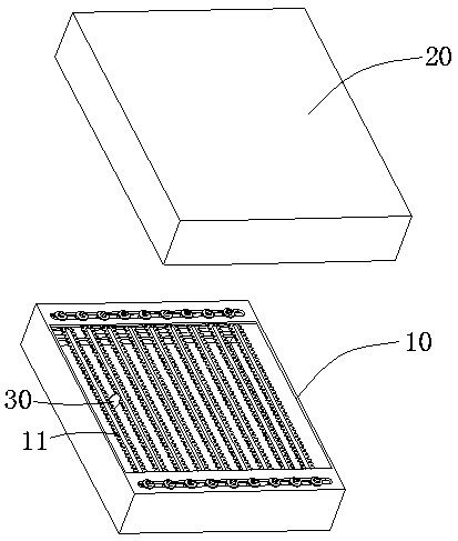
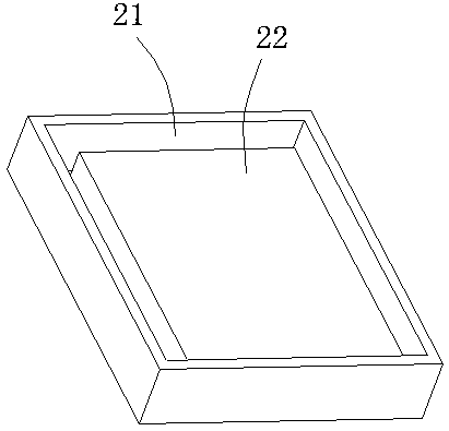
[0032] Please refer to figure 1 and figure 2 , which shows a film rewinding device 100 provided by an embodiment of the present invention, which includes a swing frame 10 and a lens tray 20, a number of lenses 30 are evenly placed on the swing frame 10, and the lens tray 20 is detachable The cover is buckled on the swing frame 10. When the lens tray 20 is covered with the swing frame 10, the relative position between the lens tray 20 and the swing frame 10 is fixed, and the lens tray 20 The layout limits that each lens 30 cannot break away from the swing frame 10 .

[0033] Specifically, in the above-mentioned embodiment, the swing frame 10 has several sawtooth bars 11, and the several sawtooth bars 11 are arranged at equal intervals along the width direction of the swing frame 10, and the lenses 30 are sandwiched between adjacent Between the two sawtooth bars 11 , every N lenses 30 among the plurality of lenses 30 are arranged in a row along the length direction of the swi...

Embodiment 2

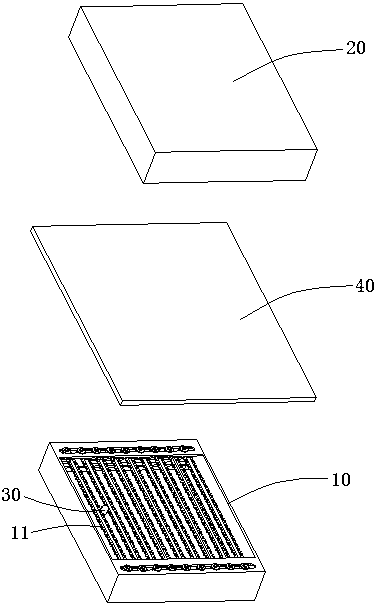
[0037] Please refer to image 3 , which shows another film rewinding device 100 provided by the embodiment of the present invention, which includes a swing frame 10 and a lens tray 20 . The difference between this embodiment and the first embodiment is that the film rewinding device 100 of this embodiment further includes an isolation layer 40 .

[0038] Specifically, the isolation layer 40 is placed between the lens tray 20 and the swing frame 10 , and both sides of the isolation layer 40 are respectively in contact with the lens tray 20 and each lens 30 . In this embodiment, the isolation layer 40 is a piece of white paper, but of course it can also be other types of articles. The effect of the isolation layer 40 is similar to that of the above sponge layer 22 , both are to prevent the lens 30 from directly contacting the lens disk 20 , and the isolation layer 40 and the sponge layer 22 form a double layer of protection. At the same time, since the isolation layer 40 is in...

Embodiment 3

[0041] Please refer to Figure 4 , which shows another film rewinding device 100 provided by the embodiment of the present invention, which includes a swing frame 10 and a lens tray 20 . The difference between this embodiment and the second embodiment is that the swing frame 10 and the lens tray 20 in this embodiment can be engaged with each other, so as to limit the position of the swing frame 10 and the lens tray 20 .

[0042] Specifically, a buckle 23 is provided on one side of the lens disc 20, and a buckle groove 12 is provided at a position corresponding to the buckle 23 on the swing frame 10. When the lens disc 20 is buckled and covered on the When the swing frame 10 is above, the buckle 23 and the buckle groove 12 are engaged with each other, thereby defining the relative position of the swing frame 10 and the lens tray 20 . In this way, during the overturning process of the pendulum frame 10 and the lens disc 20, the lens 30 will not fall out due to the instability o...


PUM


Abstract

The invention provides a lens reversing device and method. The lens reversing device comprises a swing frame and a lens disc, wherein a plurality of lenses are uniformly placed on the swing frame, thelens disc is separably buckled above the swing frame, when the lens disc and the swing frame are buckled, the relative position between the lens disc and the swing frame is fixed, and the layout of the lens disc limits each lens not to be separated from the swing frame. The lens disc is buckled on the swing frame, so the relative position between the lens disc and the swing frame is fixed, and the lens is kept on the swing frame without moving; the lens disc and the swing frame are turned over together so that the lens disc is in a state of bearing the lenses on the swing frame, at the moment, after the swing frame is removed from the lens disc, the multiple lenses can correspondingly fall into the lens disc, and the lenses cannot be damaged; when the lenses need to be taken, the lenses can be directly taken from the lens disc, and the lenses do not need to be taken from the swing frame one by one, so inspection lens taking efficiency and inspection lens mounting efficiency are improved.

Description

technical field [0001] The invention belongs to the field of lens production, in particular to a film rewinding device and a film rewinding method. Background technique [0002] During the production process of the lens of the camera, operations such as inspection and loading of the lens are required. Before the lens is inspected, the lenses are placed in the rack for the convenience of water washing or ultrasonic cleaning of the lens, so that when the lens needs to be inspected, the lens must be removed from the rack when the lens needs to be taken. Remove them one by one. [0003] However, it is relatively inconvenient to take the lenses one by one from the swing frame, and more time will be wasted in the process of checking the taking and loading of the lenses, and the production efficiency is low. Contents of the invention [0004] The technical problem to be solved by the present invention is to provide a film rewinding device and a film rewinding method, aiming at ...

Claims


Application Information

Patent Timeline
Patent Type & Authority Applications(China)
IPC IPC(8): B65G47/74B65G47/248
CPCB65G47/248B65G47/74
Inventor 曾玲
Owner 曾玲
Why Eureka
Try Eureka