Grass scraping device for preventing grass winding of rotary cultivator cutter shaft

A technology of rotary tiller and cutter shaft, which is applied in the field of rotary tiller, and can solve problems affecting the normal use of the rotary tiller, winding, and the rotary tiller shaft cannot be rotated, etc.

Active Publication Date: 2020-10-27
江苏金云农业装备有限公司
View PDF6 Cites 0 Cited by
  • Summary
  • Abstract
  • Description
  • Claims
  • Application Information

AI Technical Summary

Problems solved by technology

[0004] However, when using a rotary tiller, the port of the rotary tiller shaft is connected to the rotary tiller body. If the connection is entangled by weeds, it will affect the rotation of the rotary tiller shaft, and even cause the rotary tiller shaft to be damaged. It cannot be rotated, which affects the normal use of the rotary tiller. Although there is an operation that can scrape the blade shaft, it can only be scraped

Method used


Image

  • Grass scraping device for preventing grass winding of rotary cultivator cutter shaft
  • Grass scraping device for preventing grass winding of rotary cultivator cutter shaft
  • Grass scraping device for preventing grass winding of rotary cultivator cutter shaft

Examples


Embodiment 1

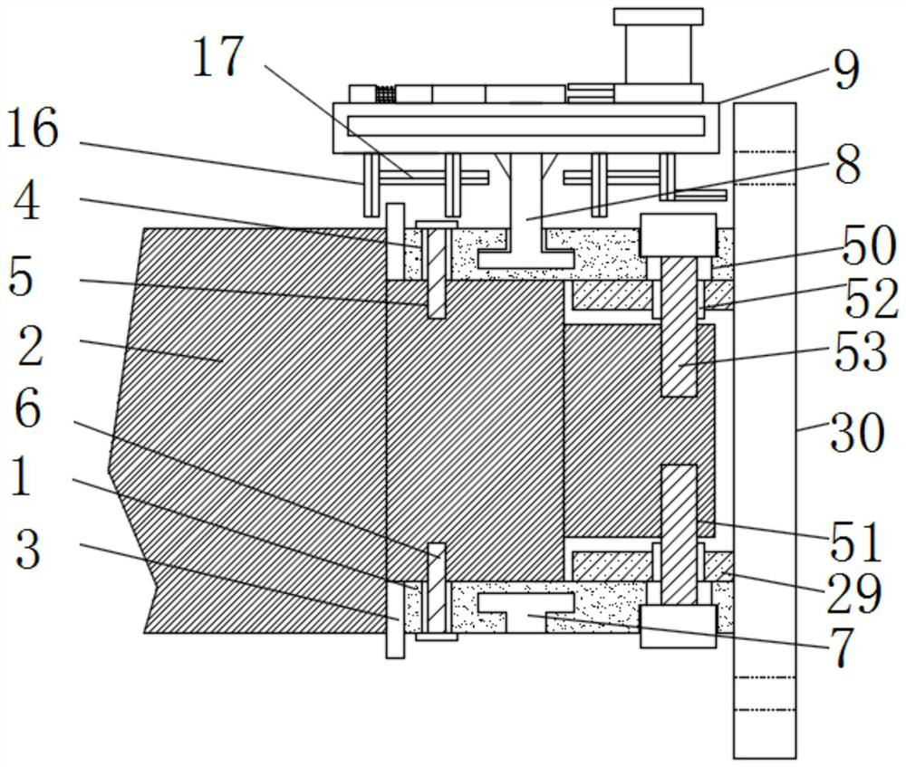
[0040] see Figure 1-10 , according to an embodiment of the present invention, a grass-scraping device for preventing the blade shaft of a rotary tiller from being entangled with grass includes two arc-shaped plates 1, and the two arc-shaped plates 1 can form a cylinder, and the arc-shaped plates 1 are connected by a connecting mechanism. The two arc-shaped plates 1 are located on the outer surface of the port of the cutter shaft 2. One side of the arc-shaped plates 1 is fixedly connected with a bonding plate 3. The bonding plate 3 is made of rubber material. The fitting plate 3 is in contact with the port of the knife shaft 2, and a through hole 4 is opened on the outer surface of the arc-shaped plate 1 and close to the fitting plate 3, and the knife shaft 2 is close to the through hole 4 There is a screw hole 5, and the port of the connecting bolt one 6 passes through the through hole one 4 and is threadedly connected with the screw hole 5;

[0041] The outer middle part of...

Embodiment 2

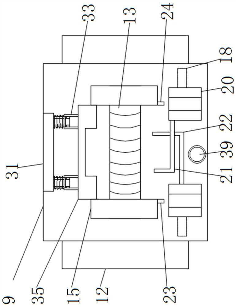
[0046] see Figure 3-6 , the fixing mechanism includes a fixing plate 31, a sleeve two 32, a sleeve three 33, a spring two 34 and a limit plate 35, and one side of the top of the fixing box 9 is fixedly connected with a fixing plate 31, and the fixing plate 31 is close to One side of the movable opening 13 is fixedly connected with two sleeves 32, and the outer surface of the sleeve two 32 is provided with a sleeve three 33, and the sleeve three 33 and the fixed plate 31 There is a spring two 34 connected therebetween, and the spring two 34 is wound on the outer surface of the sleeve two 32, and the side of the sleeve three 33 away from the fixed plate 31 is fixedly connected to the limiting plate 35, and the fixing mechanism The connection block 2 15 can be fixed, and the current state of the connection block 15 can be maintained, so that the connection block 2 15 cannot be moved, and the second limit mechanism 32 and the third sleeve 33 are connected The second limiting mec...

Embodiment 3

[0048] see image 3 and Figure 11-12 The limit mechanism one includes a threaded sleeve one 39, a threaded block 40, a support sleeve 41, a spring three 42, a limit rod two 43 and a stopper 44, and the top of the fixed box 9 is located between the movable block 20 A threaded sleeve one 39 is fixedly connected between them, and the inner thread of the threaded sleeve one 39 is connected with a threaded block 40, and the top of the threaded block 40 is fixedly connected with a support sleeve 41, and the inside of the support sleeve 41 is connected with the spring three 42. The two limit rods 43 are connected, the top of the two limit rods 43 is fixedly connected with a stopper 44, the two sides of the support sleeve 41 are opened with a limit groove two 45, and the inside of the two limit grooves 45 is provided with a limit Block three 46, the stop block three 46 is fixedly connected with the stop bar two 43, the stop mechanism one can cooperate with the rotary tiller body, an...


PUM


Abstract

The invention discloses a grass scraping device for preventing grass winding of a rotary cultivator cutter shaft. The grass scraping device comprises two arc-shaped plates, wherein the arc-shaped plates are connected through a first connecting mechanism; a sliding groove is formed in the middle of the outer side of each arc-shaped plate; the bottom end of a sliding rod is located in the sliding groove and matched with the sliding groove; a fixed box is fixedly connected to the top of the sliding rod; a first spring is arranged in the fixed box; movable plates are fixedly connected to the two sides of the first spring; blades are fixedly connected to the sides, away from the first spring, of the movable plates; a plurality of vertical weeding knives are fixedly connected to the two sides ofthe bottom of the fixed box, and transverse weeding knives are connected between the vertical weeding knives; a fixing mechanism is arranged at the top of the fixed box and located on one side of a movable opening; a first sleeve is arranged on one side of each arc-shaped plate; and the first sleeve is fixedly connected with a flange plate. The grass scraping device has the beneficial effects that weeds can be cut off before the weeds are wound on the cutter shaft, and the possibility that the weeds are wound on the cutter shaft is reduced.

Description

technical field [0001] The invention relates to the technical field of rotary tillers, in particular to a grass scraping device for preventing the cutter shaft of the rotary tiller from being entangled with grass. Background technique [0002] A rotary tiller is a tillage machine that is matched with a tractor to complete plowing and harrowing operations. It has been widely used because of its strong soil breaking ability and flat surface after plowing. At the same time, it can chop up the root stubble buried below the surface, which is convenient for the seeder to operate and provides a good seed bed for later sowing. [0003] A driven soil tillage machine with rotating cutter teeth as the working part, also known as a rotary tiller. According to the configuration of the rotary tiller shaft, it is divided into two types: horizontal axis type and vertical axis type. The horizontal-axis rotary tiller with the knife shaft horizontally placed is widely used, and it has a stro...

Claims


Application Information

Patent Timeline
IPC IPC(8): A01B33/16
CPCA01B33/16Y02P60/20
Inventor 司良永
Owner 江苏金云农业装备有限公司
Why Eureka
Try Eureka