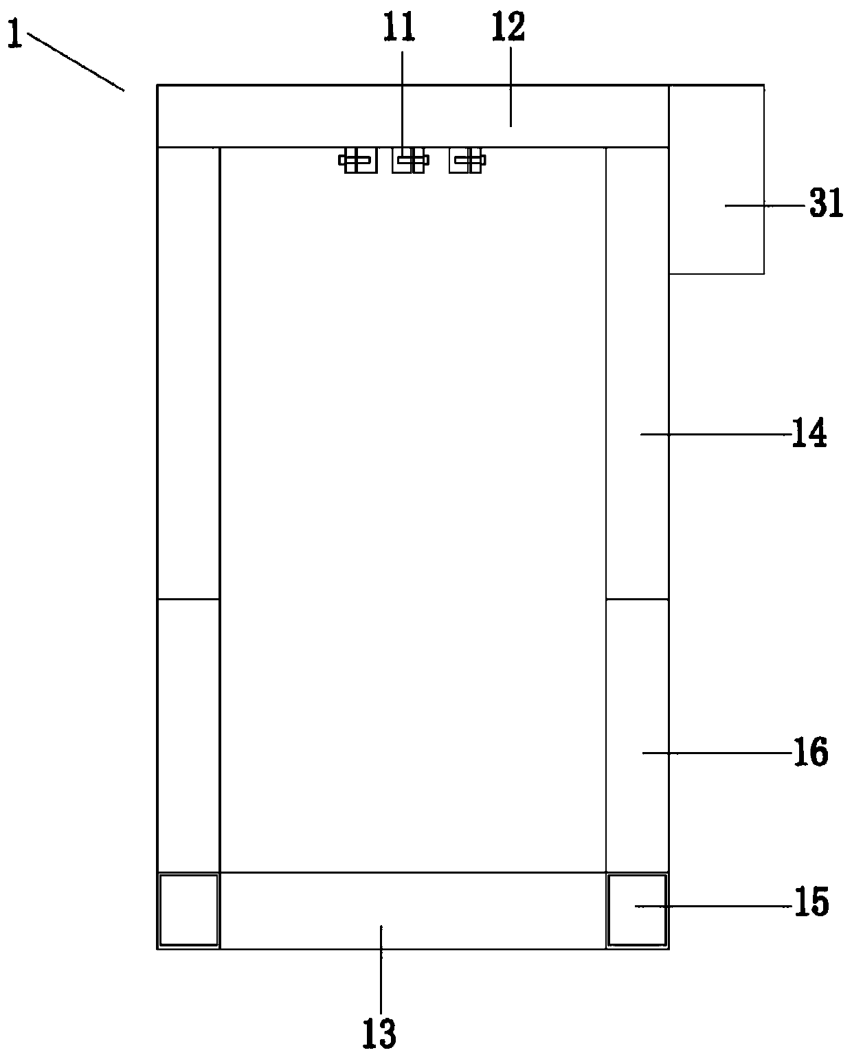
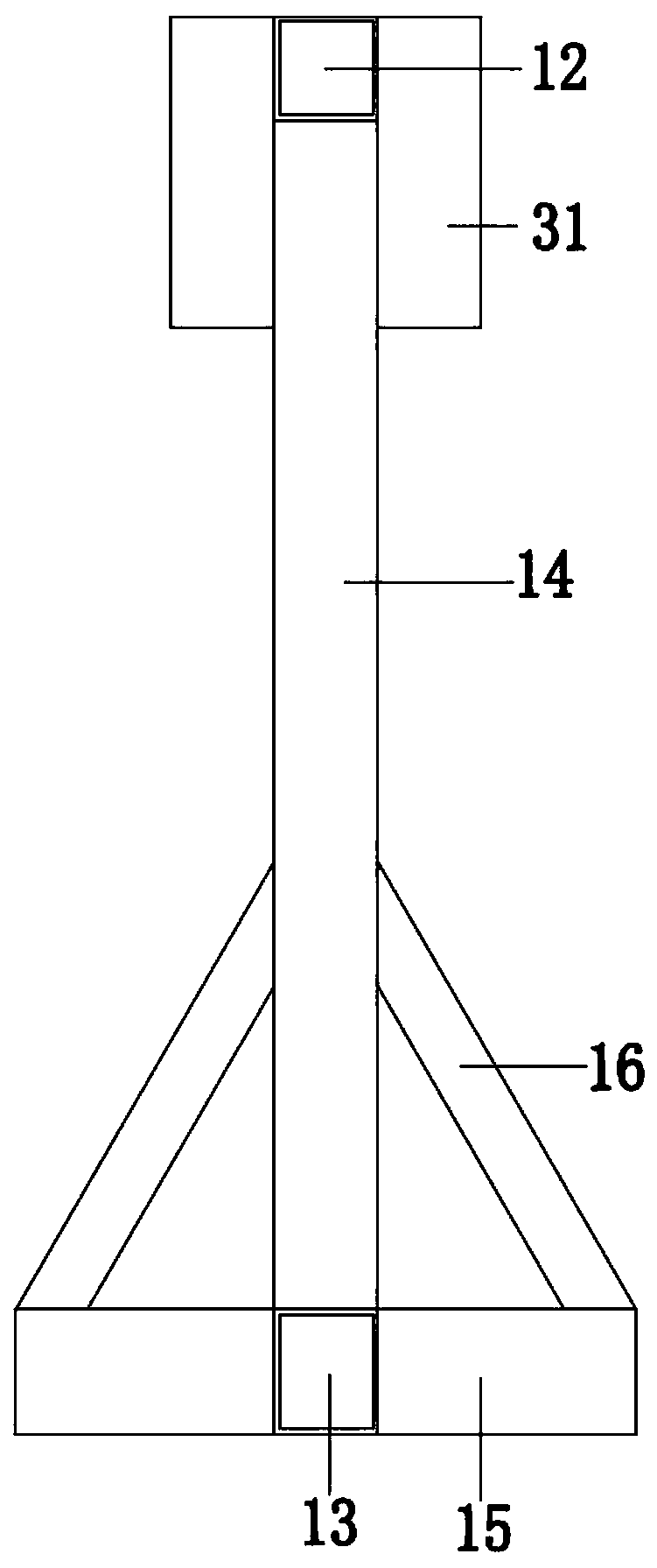
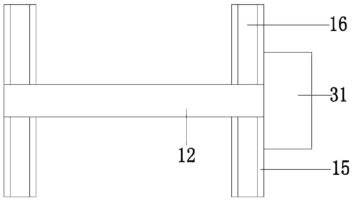
Free vibration experiment device
An experimental device and free technology, applied in educational appliances, instruments, teaching models, etc., can solve the problems of lack of experimental equipment for free vibration teaching and research, lack of perceptual knowledge, poor grasp of free vibration knowledge, etc., to facilitate popularization and popularization. The effect of simple application, simple equipment and safe use
- Summary
- Abstract
- Description
- Claims
- Application Information
AI Technical Summary
Problems solved by technology
Method used
Image
Examples
Embodiment 1
[0063] Such as Figure 8 , 9 , 10, and 14, the above-mentioned experimental device is used to simulate the bending-shaped translational vibration mode.
[0064] The vibrating rod 2 is one that is fixedly installed under the upper beam 12 through the clamp 11 .
[0065] The mass blocks are two mass balls 4 arranged up and down along the extending direction of the vibrating rod 2 , detachably connected to the vibrating rod 2 , and movable and fixedly connected to the vibrating rod 2 . Each mass sphere 4 is composed of two hemispheres 41 , the two hemispheres 41 are connected by screws 7 , and the opposite surfaces of the two hemispheres 41 form a clamping surface extending vertically downward for clamping the vibrating rod 2 . A vertical groove 8 is provided at the center of the opposing surfaces of the two hemispheres 41 . The cross section of the vertical groove 8 is an isosceles right triangle, which is convenient for clamping the circular vibrating rod 2 . Adjusting the t...
Embodiment 2
[0069] Such as Figure 11 , 12 , 13, and 14, the shear-shaped horizontal vibration mode was simulated using the above-mentioned experimental setup.
[0070] The vibrating rods 2 are two fixedly installed under the upper beam 12 through the clamp 11, and the two vibrating rods 2 are arranged in parallel.
[0071] The mass blocks are two mass plates 5 arranged up and down along the extending direction of the vibrating rod 2 , and each mass plate 5 includes a middle plate 51 and two splints 52 detachably and fixedly connected to both ends of the middle plate 51 . The middle plate 51 is connected with the clamping plate 52 by screws 7 , and a clamping surface extending vertically downwards for clamping the vibrating rod 2 is formed between the clamping plate 52 and the middle plate 51 . A vertical groove 8 is provided at the center of the opposite surface of the middle plate 51 and the splint 52 . The cross section of the vertical groove 8 is an isosceles right triangle, which i...
Embodiment 3
[0075] Such as Figure 15 , 16 , 17, and 18, the torsional vibration mode was simulated using the above experimental setup.
[0076] The vibrating rod 2 is one that is fixedly installed under the upper beam 12 through the clamp 11 .
[0077] The mass blocks are two mass rods 6 arranged up and down along the extending direction of the vibrating rod 2 , and each mass rod 6 includes a middle rod 61 and solid balls 62 fixedly connected to both ends of the middle rod 61 . Both ends of the middle rod 61 are respectively formed with threaded rods 611, and the solid ball 62 is provided with a threaded hole 621 matched with the threaded rod 611. The cooperation between the threaded rod 611 and the threaded hole 621 realizes the fixed connection between the middle rod 61 and the solid ball 62. . A U-shaped groove 612 is formed in the middle of the middle rod 61 , and an insert 613 that matches the U-shaped groove 612 and is detachably and fixedly connected is arranged in the U-shaped...
PUM
 Abstract
Description
Claims
Application Information
 - R&D
- Intellectual Property
- Life Sciences
- Materials
- Tech Scout
- Unparalleled Data Quality
- Higher Quality Content
- 60% Fewer Hallucinations
Browse by: Latest US Patents, China's latest patents, Technical Efficacy Thesaurus, Application Domain, Technology Topic, Popular Technical Reports.
© 2025 PatSnap. All rights reserved.Legal|Privacy policy|Modern Slavery Act Transparency Statement|Sitemap|About US| Contact US: help@patsnap.com


