Novel flow-type biochip flow layer architecture synthesis design method

A biochip and synthetic design technology, applied in computer-aided design, computing, special data processing applications, etc., can solve the problems of waste of resources, long scheduling time, etc., and achieve the effect of large search solution space and reasonable scheduling diagram

Active Publication Date: 2020-04-03
FUZHOU UNIVERSITY
View PDF2 Cites 3 Cited by
  • Summary
  • Abstract
  • Description
  • Claims
  • Application Information

AI Technical Summary

Problems solved by technology

It can be found that the scheduling time of the actual scheduling diagram is almost twice that of the preset scheduling diagram, and it causes a serious waste of resources

Method used


Image

  • Novel flow-type biochip flow layer architecture synthesis design method
  • Novel flow-type biochip flow layer architecture synthesis design method
  • Novel flow-type biochip flow layer architecture synthesis design method

Examples


Embodiment Construction

[0050] The technical solution of the present invention will be specifically described below in conjunction with the accompanying drawings.

[0051] The present invention provides a novel method for the synthesis and design of fluidized biochip fluidized layer framework, comprising the following steps:

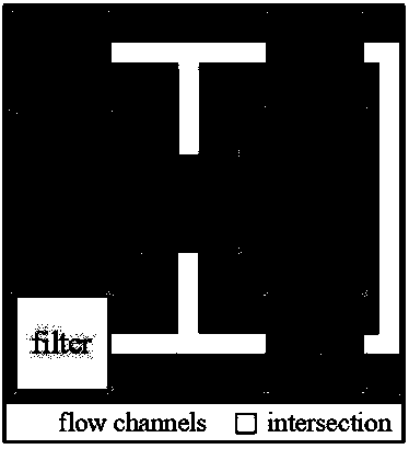
[0052] Step S1, set the current temperature T n is the initial temperature T o , generate an initial random layout solution Z according to the initially given number of components l , at this time, the component is abstracted into a point, and without loss of generality, the components are made to be the same size. In the process of generating the layout, the distance between any two points must not be less than the minimum distance, leaving room for subsequent wiring;

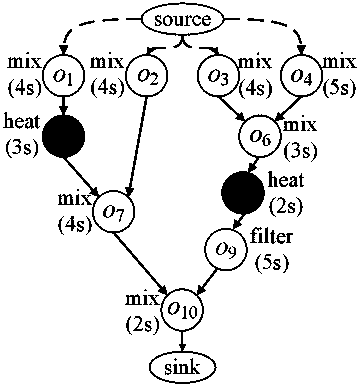
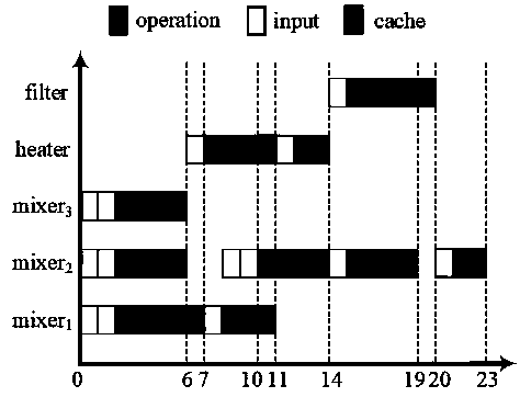
[0053] Step S2. Starting from the obtained relative positions of the components, perform binding and scheduling operations on the biochemical protocol, and obtain the scheduling result S l ;

[0054] Step S...


PUM


Abstract

The invention relates to a novel flow-type biochip flow layer architecture synthesis design method. A simulated annealing algorithm is adopted in the layout stage, a list scheduling algorithm is adopted in the binding and scheduling stage, and an improved A* path-finding algorithm based on a negotiation mechanism is adopted in the wiring stage. According to the method provided by the invention, ascheduling solution comprehensively generated by the high level has a better guiding effect on the design of the subsequent wiring stage.

Description

technical field [0001] The invention relates to a novel synthetic design method of a flow type biochip flow layer framework. Background technique [0002] The published synthetic design methods of fluidized biochip fluidized layer architecture are mainly divided into two types: the first is the traditional industrial manual design method, which requires manual operation of component placement and wiring. There is still the possibility of operation on a small scale, but it is difficult to effectively design large-scale biochemical protocols, and this design is prone to errors, and requires high knowledge reserves and personal abilities of technicians; [0003] The second is a top-down design flow that uses computer software to automate the generation of place-and-route results. Compared with the first design method, it has made obvious progress, but its design process still has a fatal flaw-the scheduling results generated during high-level synthesis have an important guidin...

Claims


Application Information

Patent Timeline
IPC IPC(8): G06F30/392G06F30/398
Inventor 董晨黄辉昌陈国龙郭文忠黄兴熊子奇
Owner FUZHOU UNIVERSITY
Why Eureka
Try Eureka