
Continuous assembling device for injector

A technology for assembling equipment and syringes, which is applied in the direction of assembly machines, metal processing equipment, metal processing, etc., and can solve problems such as low efficiency and damage

Inactive Publication Date: 2020-04-10
DONGGUAN KAILEDI NUMERICAL CONTROL SCI & TECH CO LTD
View PDF0 Cites 2 Cited by
  • Summary
  • Abstract
  • Description
  • Claims
  • Application Information

AI Technical Summary

Problems solved by technology

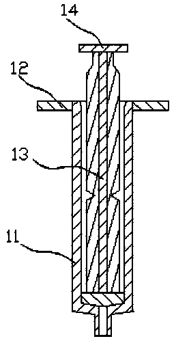
[0002] A syringe is a common medical item such as figure 2 As shown, it includes a cylinder 11 and a piston 12 inserted into the cylinder 11, the lower part of the piston is in sealing fit with the cylinder 11, the upper end of the cylinder 11 is provided with a block 13 outside, and the lower part of the piston 12 is provided with a pressure block 14; During the assembly process, the piston 12 needs to be inserted into the cylinder body 11. During the insertion process, if the piston 12 and the cylinder body 11 are relatively inclined, and the insertion force is too large, it is easy to be damaged. Therefore, now Some assemblies are mostly assembled manually, but the assembly is performed manually, which is inefficient

Method used


Image

  • Continuous assembling device for injector
  • Continuous assembling device for injector
  • Continuous assembling device for injector

Examples


Embodiment Construction

[0021] In order to enable those skilled in the art to better understand the technical solution of the present invention, the present invention will be described in detail below in conjunction with the accompanying drawings. The description in this part is only exemplary and explanatory, and should not have any limiting effect on the protection scope of the present invention. .

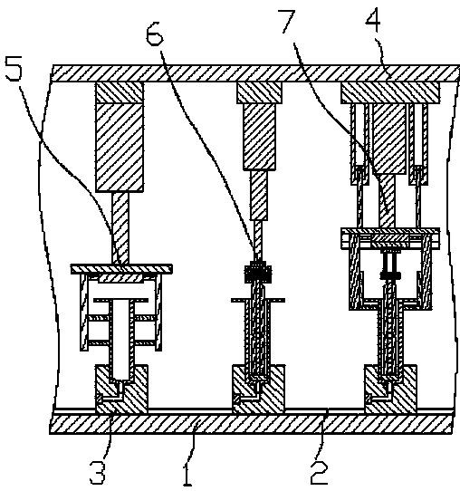
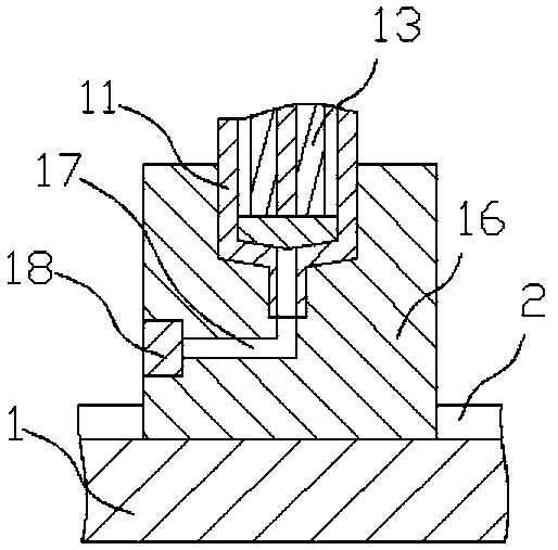
[0022] Such as Figure 1-2 As shown in and 5-6, the specific structure of the present invention is: a continuous assembly equipment for syringes, including a base plate 1 and an upper plate 4, the base plate 1 is provided with a slide rail 2, and the slide rail 2 is equipped with The carrier 3 that cooperates with the cylinder 11, the carrier 3 is equipped with a feeding device, and the cylinder feeding device 5 and the piston feeding device 6 are sequentially arranged below the upper plate 4 along the feeding direction of the carrier And unloading device 7, described piston feeding device 6 comprises...


PUM


Abstract

The invention relates to a continuous assembling device for an injector. The device comprises a bottom plate, an upper plate, a sliding rail and a carrier, the carrier is matched with a feeding device, a barrel feeding device, a piston feeding device and a discharging device are arranged below the upper plate, the piston feeding device comprises a movable feeding movable device, a piston feeding lifting air cylinder is arranged below the piston feeding movable device; the piston feeding lifting air cylinder is connected with a piston feeding lifting base, a piston feeding clamp holder is connected below the piston feeding lifting base and comprises a piston feeding clamping air cylinder below the piston feeding lifting base, the two ends of the piston feeding clamping air cylinder are connected with piston feeding clamping half blocks, the piston feeding clamping half blocks are matched with the upper surface of the pressing block, vertical piston feeding clamping air cylinders are arranged at the position, exceeding the pressing block, of the piston feeding clamping half blocks, a piston feeding clamping block matched with the lower surface of the pressing block is connected to the lower portion of the piston feeding clamping air cylinder. According to the continuous assembling device, continuous automatic assembly of the injector is achieved, and the assembly efficiency is improved.

Description

technical field [0001] The invention relates to the field of processing equipment for syringes, in particular to continuous assembly equipment for syringes. Background technique [0002] A syringe is a common medical item such as figure 2 As shown, it includes a cylinder 11 and a piston 12 inserted into the cylinder 11, the lower part of the piston is in sealing fit with the cylinder 11, the upper end of the cylinder 11 is provided with a block 13 outside, and the lower part of the piston 12 is provided with a pressure block 14; During the assembly process, the piston 12 needs to be inserted into the cylinder body 11. During the insertion process, if the piston 12 is relatively inclined to the cylinder body 11 and the insertion force is too large, it is easy to be damaged. Therefore, now Most of the assembly is manually assembled, but the manual assembly is inefficient. Contents of the invention [0003] The purpose of the present invention is to provide a continuous ass...

Claims


Application Information

Patent Timeline
IPC IPC(8): B23P21/00
CPCB23P19/001B23P21/004
Inventor 文婵丘强邱广文陈马鑫
Owner DONGGUAN KAILEDI NUMERICAL CONTROL SCI & TECH CO LTD
Learn More