Chair frame

A technology of chair frame and chair back frame, which is applied in the field of chair frame, which can solve the problems of human body fatigue, large backrest, and easy tipping of the chair, and achieve the effect of improving comfort, improving stability and reducing difficulty

Pending Publication Date: 2020-04-21
HENGLIN HOME FURNISHINGS CO LTD
View PDF2 Cites 0 Cited by
  • Summary
  • Abstract
  • Description
  • Claims
  • Application Information

AI Technical Summary

Problems solved by technology

[0006] 1) The center of gravity of the human body and the chair is moved backward, and the chair is easy to tip backward;
[0007] 2) The backrest will bear a large force, so it is necessary to improve the material and structural stability of the backrest, thereby increasing the production cost;
[0008] 3) Correspondingly, the chair mainly provides support to the back of the human body through the backrest, while the sitting back only has a role in fixing the position of the buttocks of the human body, which does not conform to the force of the human body when it is usually lying down, so that the human body The overall body is not in a comfortable state. After lying on the back for a long time, the human body will feel more tired

Method used


Image

  • Chair frame
  • Chair frame
  • Chair frame

Examples


Embodiment 1

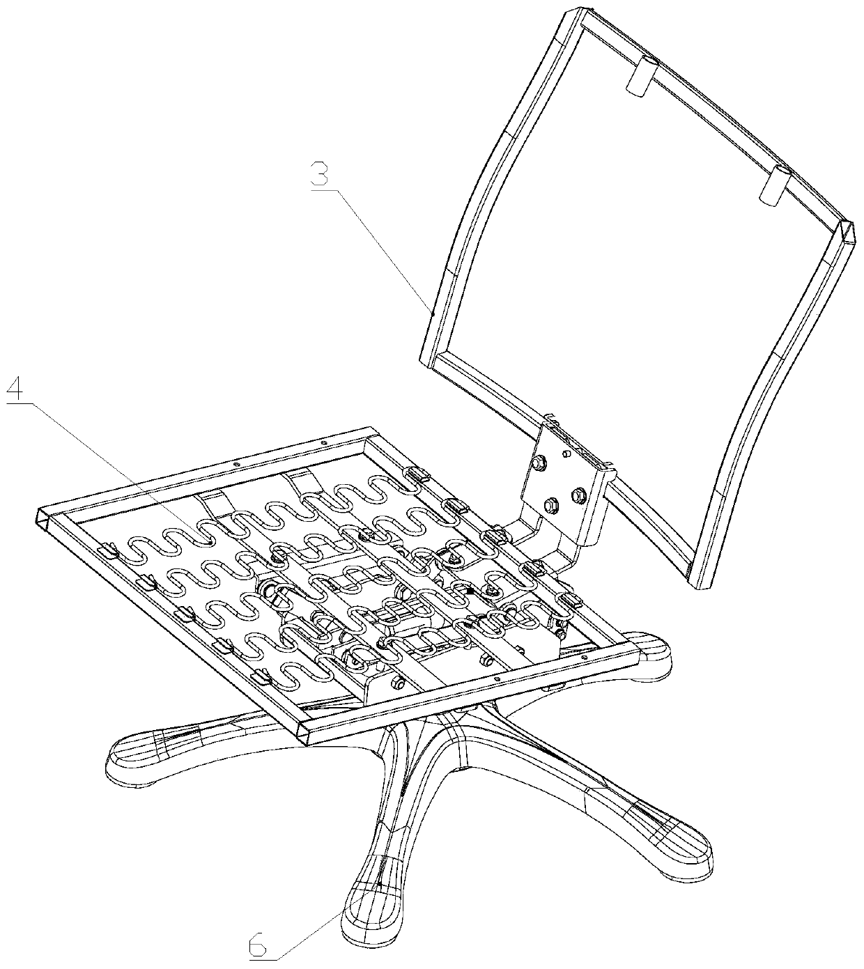
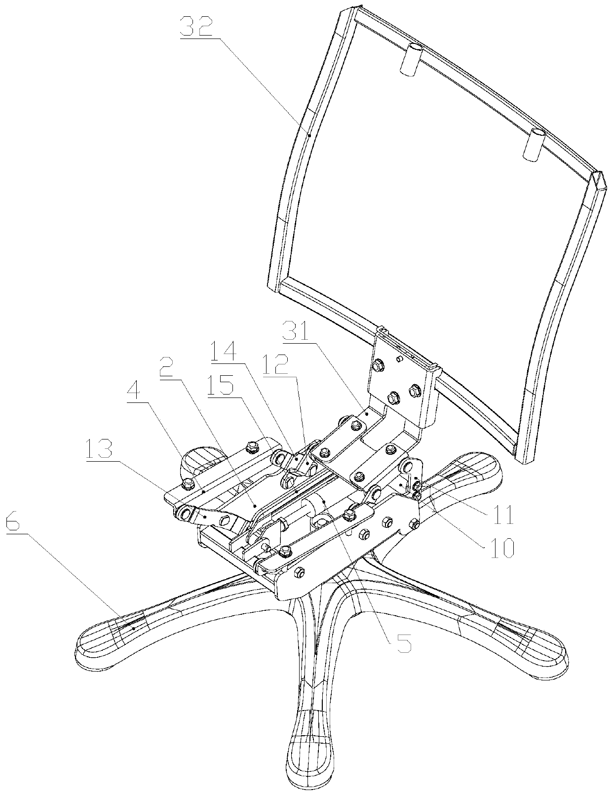
[0041] Such as Figure 1-4 As shown, a chair frame includes a foot 6, a fixed seat 2, a seat back frame 3 and a seat frame 4, the fixed seat 2 is fixedly connected with the foot 6, and the seat back frame 3 and the seat frame 4 are movably installed on a fixed seat 2;

[0042] The fixed seat 2 includes a bottom plate 21, two side plates 22 on both sides of the bottom plate 21, and a fixed rod 23 connected to the front half of the two side plates 22, the two side plates 22 are connected to the bottom plate 21 and the fixed rod 23 Fixed connection or one-piece molding;

[0043] Described chair back frame 3 comprises chair back frame 32 and connecting frame 31, and described connecting frame 31 comprises horizontal frame and vertical frame, and the included angle between described horizontal frame and vertical frame is between 90 degree and 120 degree , the vertical frame is fixedly connected or integrally formed with the lower end of the seat back frame 32;

[0044] The seat ...

Embodiment 2

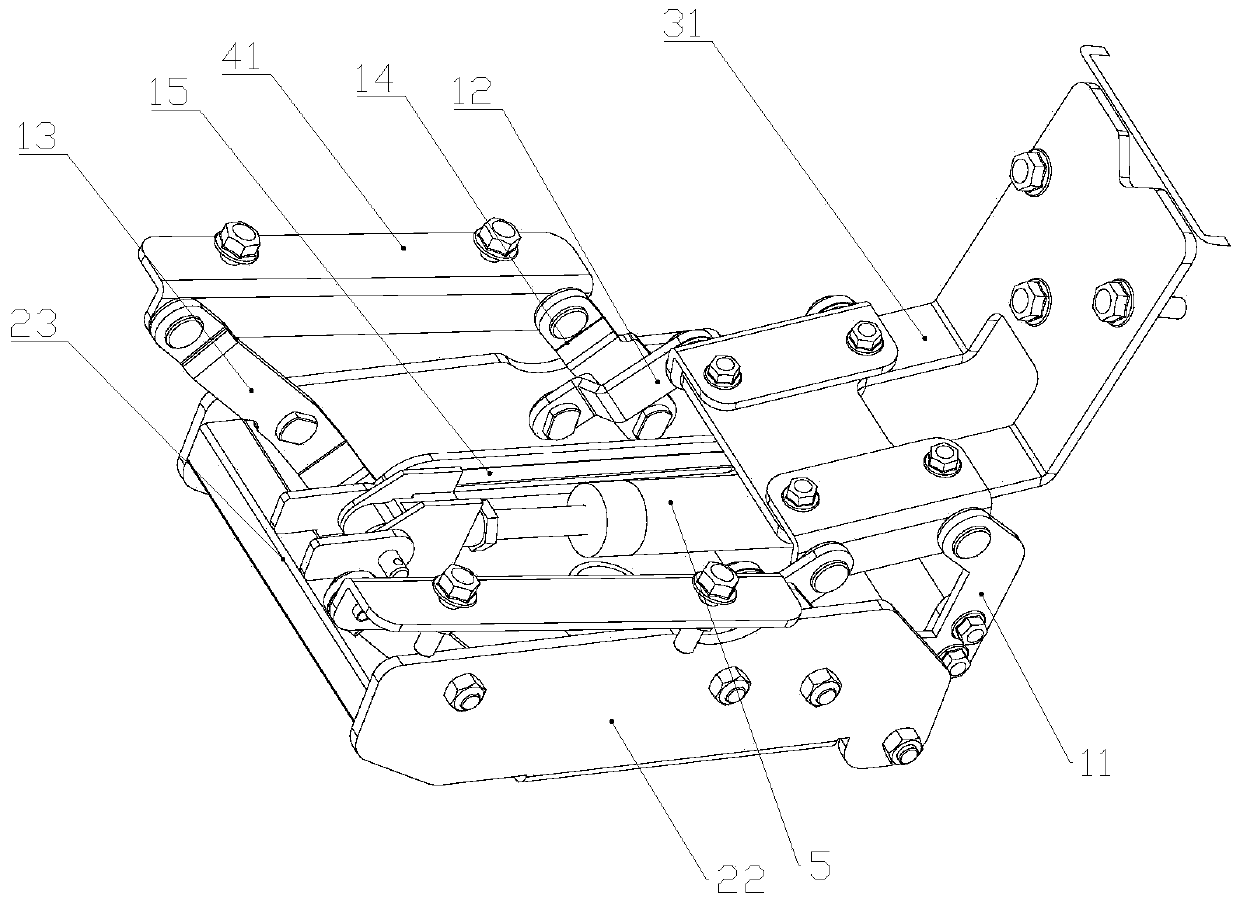
[0065]The difference between this embodiment and Embodiment 1 is that when the retractable device is stretched, the angle of the backrest tilting increases, and at the same time drives the seat frame to rise and move backward. When the device is shortened, the backward tilting angle of the chair back frame is reduced, and at the same time, the chair seat frame is driven to descend and move forward.

[0066] Among them, the first positional relationship between the linkage plate and the fourth link is: when the linkage plate is located behind the fourth link, the top end of the linkage plate is always behind the bottom end of the linkage plate during the rotation process and the top end of the fourth link is rotating. During the process, it is always in front of the bottom end of the fourth link; when the linkage plate is in front of the fourth link, the top of the linkage plate is always in front of the bottom end of the linkage plate during the rotation process and the top of ...


PUM


Abstract

The invention discloses a chair frame. The chair comprises bottom feet, a fixed seat, a chair back frame, a chair seat frame, a telescopic device, a linkage rod, a left linkage plate, a right linkageplate and two fourth connecting rods, the front end of the telescopic device is hinged with the fixed seat, and the rear end of the telescopic device is hinged with the middle section of the linkage rod; the upper end of each linkage plate is hinged with the side surface of the bottom of the chair back frame; the middle sections of the two linkage plates are fixedly connected with the left end andthe right end of the linkage rod respectively, the bottom end of each fourth connecting rod is hinged to the side face of the fixed base, the top end of each fourth connecting rod is hinged to the bottom side face of the chair back frame, and the fourth connecting rod and the linkage plate on one side form a four-connecting-rod mechanism with the chair back frame and the fixed base; according tothe technical scheme, the chair back frame tilts backwards, the chair seat frame moves upwards and backwards, the chair seat frame moves forwards and downwards in the lifting process of the chair backframe, the distance between the bottom of the chair back frame and the rear portion of the chair seat frame is kept unchanged all the time, and therefore the zero displacing effect is achieved, and the back rubbing phenomenon of the back of a human body and the chair back is avoided.

Description

technical field [0001] The invention relates to the technical field of furniture, in particular to a chair frame. Background technique [0002] The comfort of the chair is directly related to the quality of people's work and life. More and more companies are researching the seat-back linkage mechanism to realize self-adaptive functions and improve seat comfort. [0003] At present, the seat-back linkage mechanism used in seats on the market has a complex structure, high difficulty in production and processing, resulting in high cost; as the Chinese patent document with the publication number CN104223821B discloses a swivel chair chassis, which is composed of a plurality of connecting rods and brackets. The frame and the base constitute a four-bar linkage mechanism. When the rocker connected to the backrest rotates, the bracket connected to the seat moves upwards and backwards as a whole, and according to the weight of the human body, the reclining force of the backrest has ...

Claims


Application Information

Patent Timeline
Patent Type & Authority Applications(China)
IPC IPC(8): A47C7/40A47C7/02A47C3/00
CPCA47C3/00A47C7/02A47C7/402
Inventor 王江林王郑兴鲍家华
Owner HENGLIN HOME FURNISHINGS CO LTD
Why Eureka
Try Eureka