Breather valve applied to non-porous drum and drum washing machine

The technology of a drum washing machine and a ventilation valve, which is applied in the field of drum washing machines, can solve the problem of dirt remaining in the inner and outer drums, and achieve the effects of improving the cleanliness, being suitable for popularization and use, and having a simple structure.

Active Publication Date: 2020-04-21
QINGDAO HAIER WASHING MASCH CO LTD +2
View PDF9 Cites 1 Cited by
  • Summary
  • Abstract
  • Description
  • Claims
  • Application Information

AI Technical Summary

Problems solved by technology

[0008] Now, because there is generally a large amount of dirt between the inner and outer cylinders of the drum washing machine, in order to avoid the pollution of the washing water, the applicant has previously proposed a non-porous drum washing machine that combines the inner and outer drums into one to overcome the gap between the inner and outer drums. The problem of dirt remaining between

Method used


Image

  • Breather valve applied to non-porous drum and drum washing machine
  • Breather valve applied to non-porous drum and drum washing machine
  • Breather valve applied to non-porous drum and drum washing machine

Examples


Embodiment 1

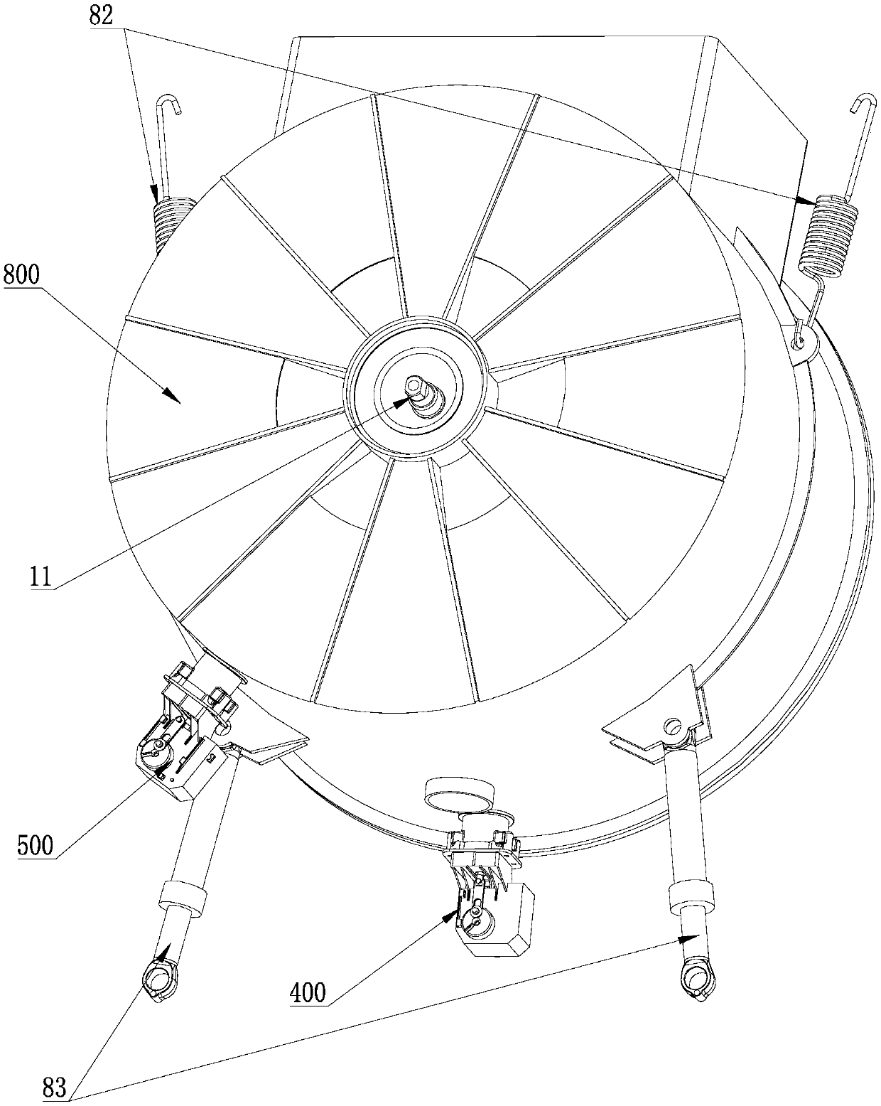
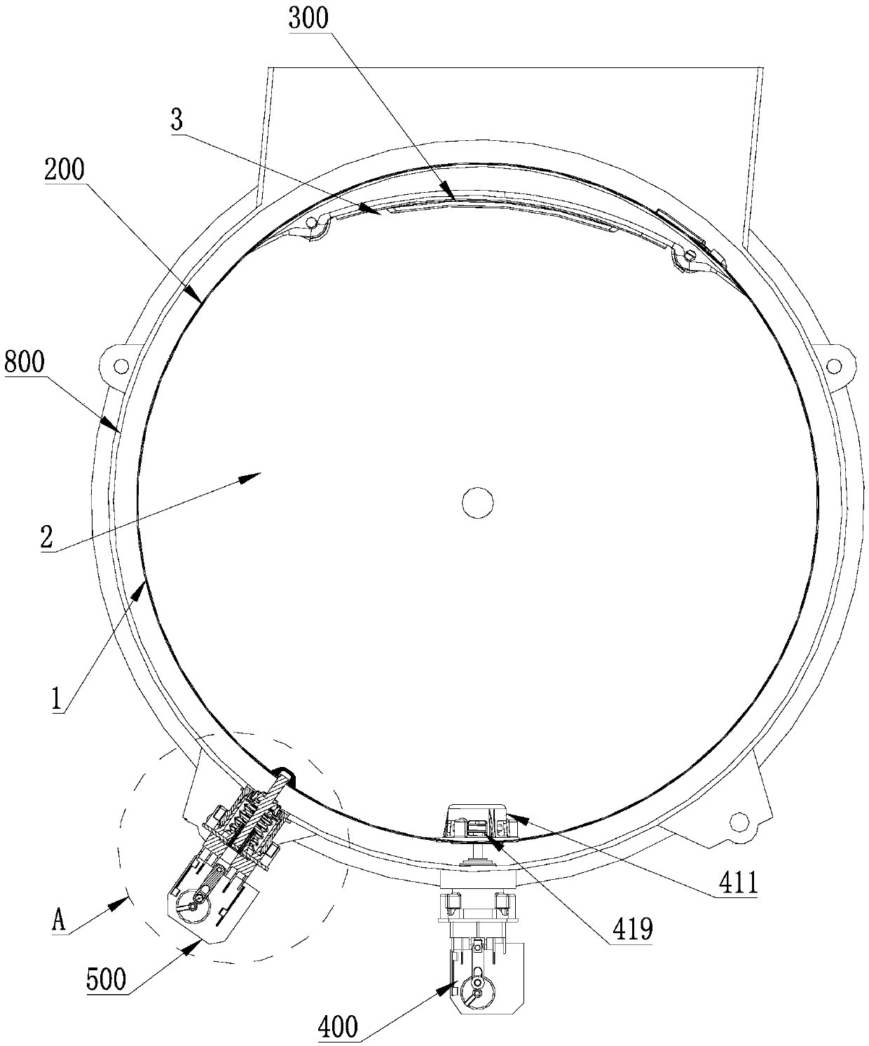
[0059] Such as Figure 1 to Figure 7 As shown, this embodiment introduces a drainage structure of a top-loading drum washing machine. The washing machine includes a drum 800 installed in the housing 100 without dehydration holes. The side wall of the drum 200 is provided with a clothes insertion port 3. 200 is provided with a door cover 300 that can be turned over to open and close the clothes input port; the drum 200 is provided with a drain port 45, and the drain port 45 is provided with a valve core 413 corresponding to the closed opening; a drain structure 400 is also installed in the housing 100, After the drum 200 rotates to a fixed position, the valve core 413 is pushed away to open the drain port 45 .

[0060] By arranging the above-mentioned structure on the drum, after the drum is rotated to a fixed position, the valve core provided at the drain outlet is correspondingly pushed open by the action of the drainage structure, so that the drain outlet of the non-porous d...

Embodiment 2

[0074] Based on the first embodiment above, this embodiment also has the following distinguishing technical features: Figure 1 to Figure 4 As shown, in order to allow the drum to rotate to a fixed position accurately, a positioning structure 500 is also provided on the drum washing machine to limit the rotation of the drum 200 to a fixed position, especially to keep the drum 200 to stop after rotating to a fixed position.

[0075] In this embodiment, the outer circumference of the drum 200 is provided with a positioning groove 55 sunken into the cylinder and a positioning rod 54 that can move telescopically along the radial direction of the drum 200. The positioning rod 54 and the positioning groove 55 are arranged in the same rotating section of the drum 200 to The telescopic end of the positioning rod 54 can extend into the positioning groove 55 correspondingly. Preferably, when the positioning rod 54 is inserted into the positioning slot 55 , the drum 200 rotates to a fixe...

Embodiment 3

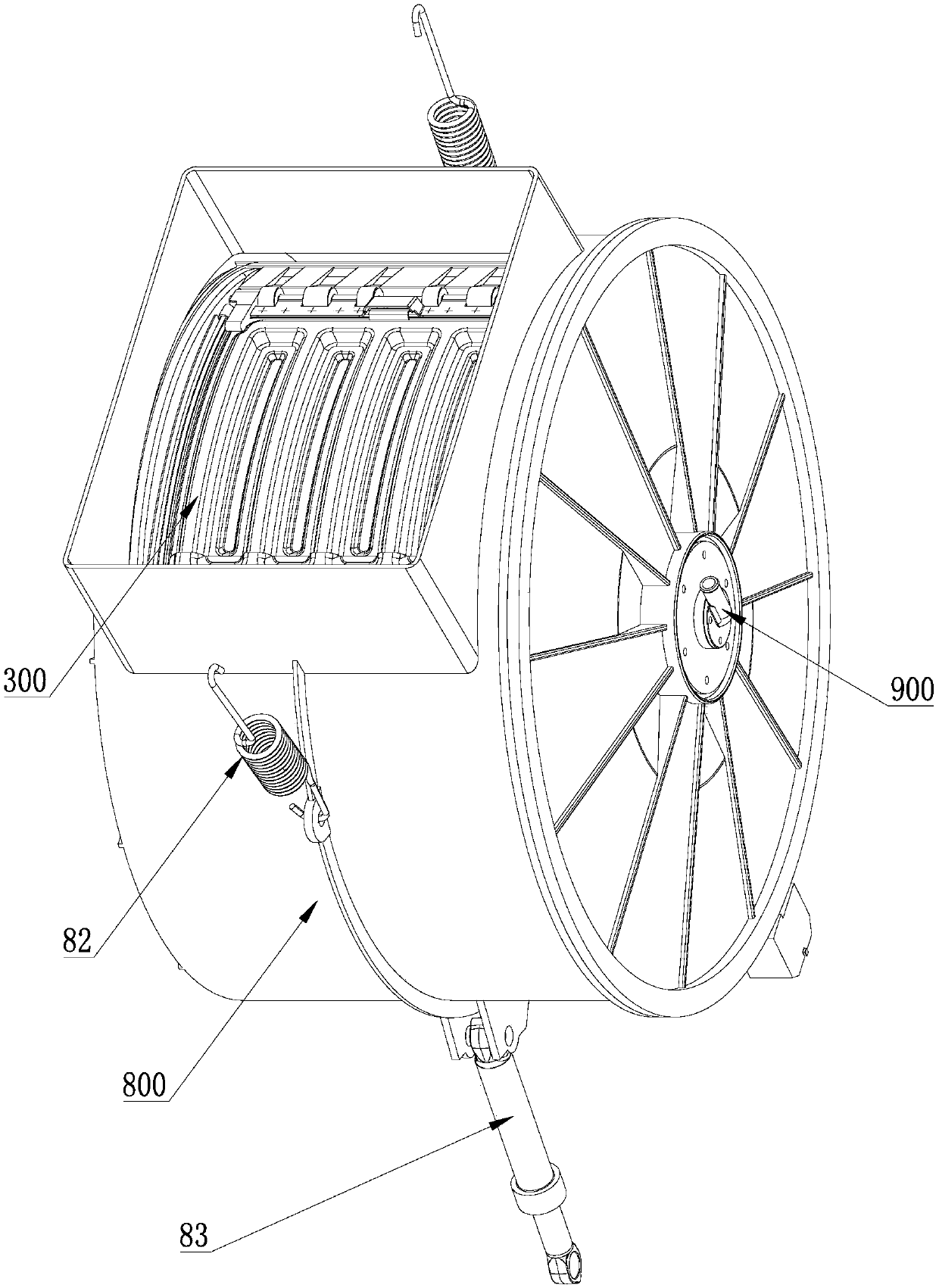
[0087] Such as Figure 8 to Figure 10 As shown, this embodiment introduces a water inlet structure 900 of a top-loading drum washing machine. The washing machine includes a drum 200 installed in the housing 100 without dehydration holes, and the side wall of the drum 200 is provided with a clothes insertion port 3 The drum 200 is provided with a door cover 300 that can be turned over to open and close the clothes inlet; the two ends of the drum 200 are sealed, and the center of the sealed end 2 is connected to the housing 100 through the rotating shaft 11 so that it can rotate relatively. At least one end of the rotating shaft 11 is formed by The hollow sleeve is formed, and the hollow part forms the flow channel 90 and communicates with the water inlet pipe of the washing machine.

[0088] By arranging the above-mentioned water inlet structure at the central rotating shaft of the drum, the use function of the top-loading washing machine to feed water into the non-porous drum ...


PUM


Abstract

The invention discloses a breather valve applied to a non-porous drum. The breather valve comprises a valve plate, and the valve plate is provided with a cleft only allowing gas to flow through; the valve plate is assembled on a mounting structure; the mounting structure comprises a bracket; the bracket comprises a disc-shaped body having a plurality of hollow-out portions; the valve plate coversthe bracket laid at one side of the disc-shaped body; and a certain distance exists between the valve plate and the disc-shaped body to leave an activity space for deformation of the valve plate. Theinvention further discloses a drum washing machine. The drum washing machine comprises the non-porous drum which is installed in a shell and does not include a dehydration hole; and the non-porous drum is provided with at least one breather hole, and the breather valve is installed on each breather hole. Through the above arrangement, the valve plate can be fixedly assembled on the breather hole of the drum, and the fixed installation of the breather valve plate is realized; and at the same time, due to the blocking effect of the bracket, the direct contact between the valve plate and clothesand water flow in the drum is avoided, thereby preventing the situation that the valve plate is directly impacted and damaged.

Description

technical field [0001] The present invention relates to washing machine equipment in household appliances, in particular to a top-loading drum washing machine, in particular to a drum washing machine whose drum is composed of a non-porous inner cylinder without dehydration holes and whose top is provided with a clothes feeding port . Background technique [0002] Washing machines can generally be classified into pulsator type, agitator type and drum type washing machines. Generally speaking, washing machines remove stains from laundry through the action of water and detergent. [0003] The pulsator washing machine performs washing operations by rotating a pulsator in the center of the washing tub left and right. The agitator washing machine uses the friction between the water flow and the laundry to perform the washing operation by rotating the rotating blade in the center of the washing tank left and right. The drum type washing machine beats the clothes by rotating the ...

Claims


Application Information

Patent Timeline
Patent Type & Authority Applications(China)
IPC IPC(8): D06F37/00D06F37/04D06F21/04D06F37/10
CPCD06F37/00D06F37/04D06F21/04D06F37/10Y02B40/00
Inventor 刘海涛李以民劳春峰许升
Owner QINGDAO HAIER WASHING MASCH CO LTD
Why Eureka
Try Eureka