Infrared beak-trimming equipment
A kind of equipment, infrared technology, applied in veterinary surgery, medical science, veterinary instruments, etc., can solve the problems of few functions, small processing capacity of beak trimming equipment, low degree of automation, etc., and achieve the effect of multiple functions
- Summary
- Abstract
- Description
- Claims
- Application Information
AI Technical Summary
Problems solved by technology
Method used
Image
Examples
Embodiment 1
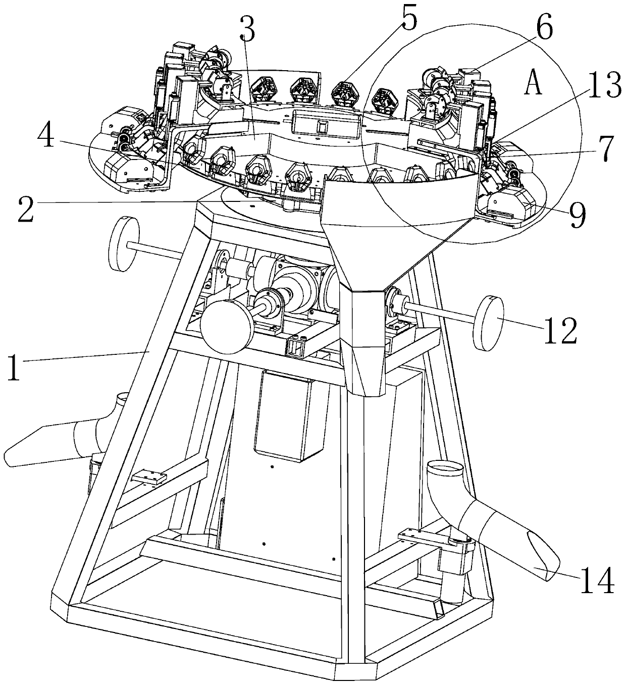
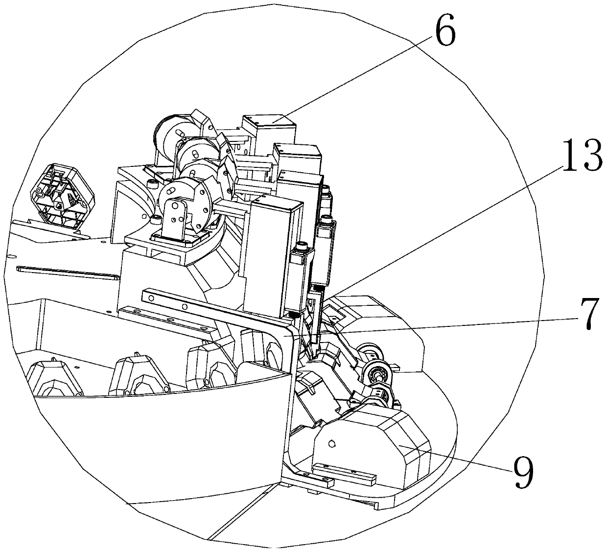
[0045] Such as Figure 1-2 As shown, the embodiment of the present invention provides an infrared beak trimming device, which includes:
[0046] bracket 1;
[0047] The rotating mechanism 2 is arranged on the top of the support 1;
[0048] The disc body 3 is fixedly arranged above the rotating mechanism 2;
[0049] The turntable 4 is arranged on the outer periphery of the disk body 3 and rotates in the horizontal direction under the drive of the rotation mechanism 2;
[0050] A plurality of chick clamps 5 are arranged at intervals on the outer edge of the turntable 4 for clamping the chicks and exposing the chicken beaks;
[0051] The injection mechanism 6 is arranged on the outer edge of the tray body 3 to inject vaccines to the chicks on the chick clamp 5;
[0052] The infrared beak trimming mechanism 7 is arranged on the outer edge of the disc body 3 to perform infrared beak trimming on the chicks on the chick clamp 5 .
[0053]The equipment of this embodiment is used ...
Embodiment 2
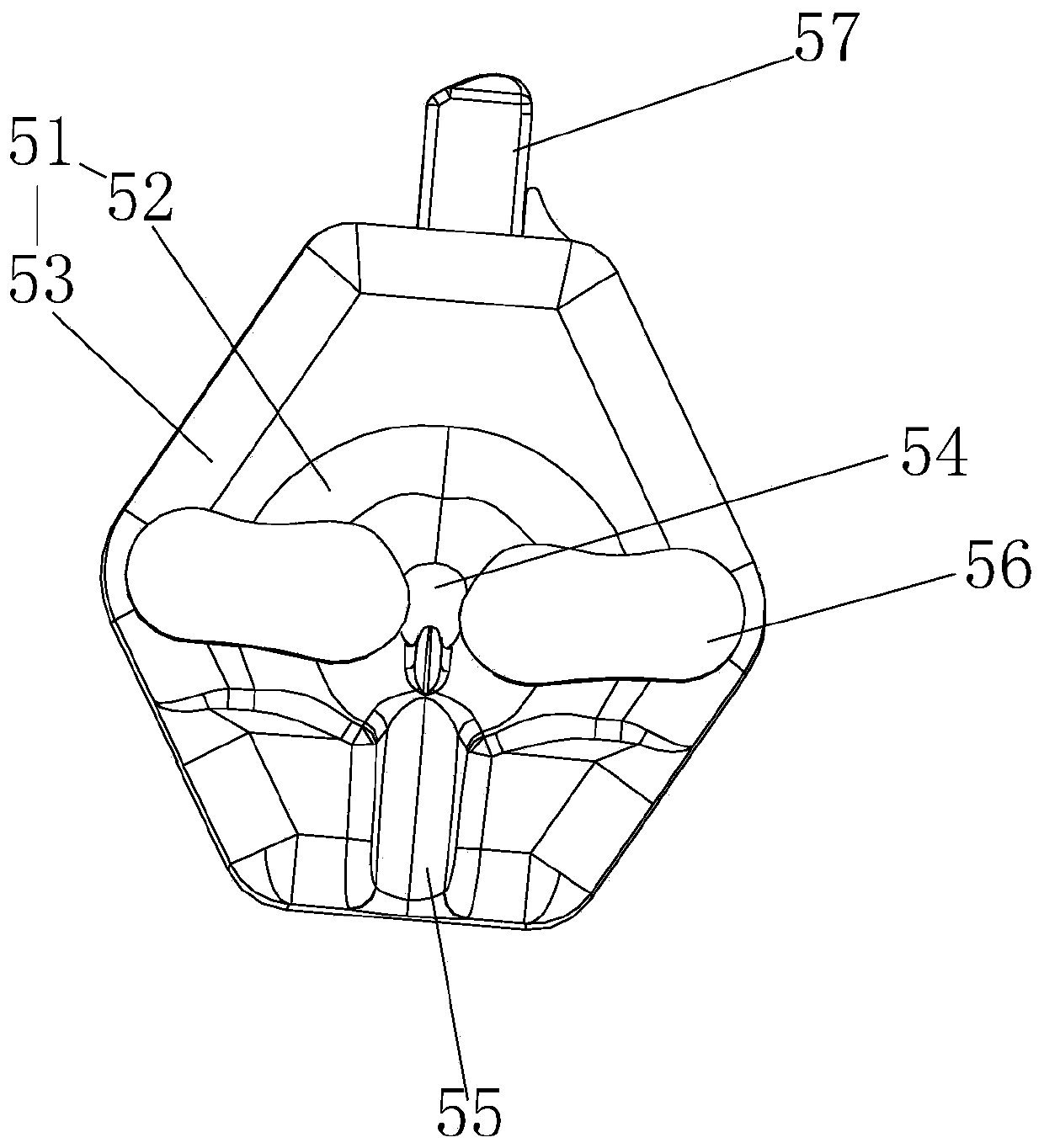
[0055] On the basis of Example 1, such as image 3 As shown, the chick clamp 5 includes a disc-shaped clamp body 51 and a fixing mechanism; the clamp body 51 has a depression 52 formed in the middle for accommodating the chicken head and a flange 53 positioned outside the depression 52, the The bottom of the depression is provided with an opening 54 for passing through the chicken beak, and the flange 53 is provided with a through groove 55 communicating with the depression 52 for accommodating the chicken neck; The movable part 56 on the 53 and the lifting part 57 for driving the movable part 56 to rotate to clamp the chicken head in the recess 52; the movable part 56 is two and is triangularly distributed with the through groove 55 .
[0056] The chick jig of this embodiment can insert the chicken head and chicken beak into the depression and opening, and then lift the puller to fix the chicken head and chicken beak through the movable part. The strip-shaped piece, the lif...
Embodiment 3
[0058] On the basis of Example 1, such as Figure 4-5 As shown, the corresponding part of the chick clamp 5 on the tray body 3 is provided with a clamping mechanism, and the clamping mechanism includes a base plate 81, an optical fiber sensor 82 and a pushing mechanism 83 arranged on the base plate 81 , the optical fiber sensor 82 senses the chicken head toward the depression 52, and the pushing mechanism 83 is connected to the lifting member 57 for pulling the lifting member when the optical fiber sensor 82 senses the chicken head 57 drives the movable part 56 to rotate to clamp the chicken head in the depression 52; the pushing mechanism 83 includes a telescopic motor, a telescopic rod connected to the telescopic motor and a transmission part of the lifting part 57, a telescopic motor connected to the base plate 81 connectors.
[0059] The clamping mechanism of this embodiment can detect the chicken head through the optical fiber sensor, and then lift the lifting member thr...
PUM
 Abstract
Description
Claims
Application Information
 - R&D
- Intellectual Property
- Life Sciences
- Materials
- Tech Scout
- Unparalleled Data Quality
- Higher Quality Content
- 60% Fewer Hallucinations
Browse by: Latest US Patents, China's latest patents, Technical Efficacy Thesaurus, Application Domain, Technology Topic, Popular Technical Reports.
© 2025 PatSnap. All rights reserved.Legal|Privacy policy|Modern Slavery Act Transparency Statement|Sitemap|About US| Contact US: help@patsnap.com


