Foundation pit excavation method

A technology for foundation pits and areas, applied in excavation, infrastructure engineering, construction, etc., can solve problems such as settlement, and achieve the effects of reducing construction volume, reducing costs, and improving work efficiency

Active Publication Date: 2020-05-08
CHINA RAILWAY 16 BUREAU GRP BEIJING METRO ENG CONSTR +1
View PDF11 Cites 0 Cited by
  • Summary
  • Abstract
  • Description
  • Claims
  • Application Information

AI Technical Summary

Problems solved by technology

[0004] The purpose of the present invention is to provide a foundation pit excavation method to solve the technical problem that using the dewatering method in the prior art to drain groundwater may easily cause a large area of ​​settlement outside the pit

Method used


Image

  • Foundation pit excavation method
  • Foundation pit excavation method
  • Foundation pit excavation method

Examples


Embodiment 1

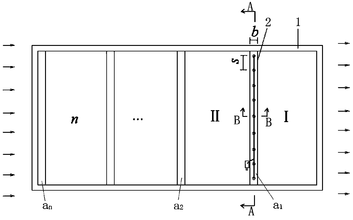
[0042] During construction, first determine the seepage direction of groundwater inside the foundation pit area to be excavated (such as figure 1 (indicated by the middle arrow), and then construct the foundation pit enclosure structure 1, and excavate the soil layer above the groundwater level, wherein, the area surrounded by the foundation pit enclosure structure 1 is the area to be excavated. It should be noted that the foundation pit enclosure structure is a conventional structure for foundation pit construction.

[0043] Such as figure 1 As shown in , the area of ​​the foundation pit to be excavated is divided into n excavation sections with roughly equal areas. Section I starts from the downstream of the groundwater seepage direction, and at the junction of sections I and II a 1 Precipitation zone 2 is set at the position, and precipitation zone 2 intersects with the groundwater seepage direction inside the foundation pit area to be excavated.

[0044] Such as Figure...

Embodiment 2

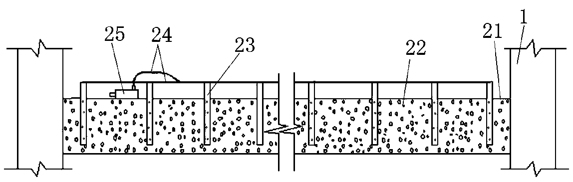
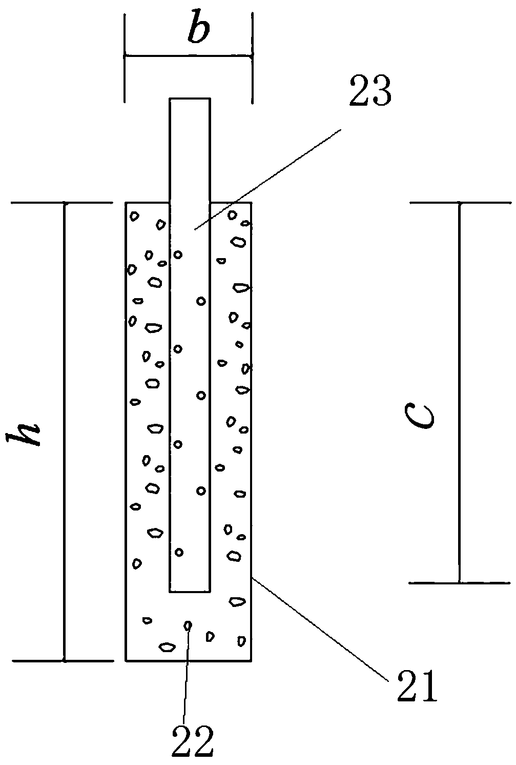
[0053] The difference from Example 1 is that the precipitation zone is composed of a plurality of precipitation wells, each precipitation well is arranged at intervals along the direction perpendicular to the groundwater seepage, the precipitation wells are filled with filter material, and a filter pipe is arranged in the filter material, and the filter pipe is connected with a drainage The drain pipe is connected with a water pump, and the water pump is used to pump out the groundwater in the dewatering well.

Embodiment 3

[0055] The difference from Example 1 is that after Section I is completed, the junction a of Sections I and II is removed first 1 The water pump, drainage pipe, water filter pipe and filter material at the place, and then at the junction of Sections II and III a 2 Dig the catchment ditch at the place, and make the junction a 1 The drainage pipes, filter pipes and filter materials at the place are put into the gutter to form a precipitation belt, and then the second section is excavated.


PUM


Abstract

The invention relates to a foundation pit excavation method. The method comprises the following steps that 1, a dewatering belt is arranged in a to-be-excavated foundation pit area, wherein the dewatering belt intersects with the seepage direction of underground water in the to-be-excavated foundation pit area, and underground water in a dewatering belt setting area through using the dewatering belt so as to block the underground water in front of the dewatering belt; 2, an area located at the downstream of the dewatering belt in the seepage direction of the underground water is excavated; 3,another dewatering belt on one side of the dewatering belt in the upstream of the seepage direction of the underground water is arranged; step 4, an area located at the downstream of the newly arranged dewatering belt in the seepage direction of the underground water is excavated. According to the foundation pit excavation method, dewatering is only carried out in the foundation pit, and thereforelarge-area sedimentation outside a pit can be avoided.

Description

technical field [0001] The invention relates to a foundation pit excavation method. Background technique [0002] When the foundation pit is excavated, groundwater is often encountered, and the method generally adopted for the treatment of groundwater is precipitation. Precipitation in cohesive soil layer, due to the small compressive modulus of the soil layer, the effective stress in the soil layer increases during the precipitation process, which may cause a large area of ​​additional settlement on the ground, resulting in deformation of surrounding buildings or underground pipelines or even destroy. [0003] If a closed water-stop curtain is used, the inside of the foundation pit still needs to be drained to drain the existing groundwater; if a non-closed water-stop curtain is used, precipitation needs to be done inside and outside the pit at the same time. Above-mentioned two kinds of water-stop curtains all have complex construction technology and high cost. Content...

Claims


Application Information

Patent Timeline
Patent Type & Authority Applications(China)
IPC IPC(8): E02D17/02E02D19/10E02D19/08E02D19/22
CPCE02D17/02E02D19/08E02D19/10E02D19/22
Inventor 石岭张文龙高飞龙孟凡立刘璞马志强王玉龙康伟蒋维周宾李永辉
Owner CHINA RAILWAY 16 BUREAU GRP BEIJING METRO ENG CONSTR
Why Eureka
Try Eureka