Electronic equipment and method of use

A technology of electronic equipment and lens modules, which is applied in the field of photography, can solve problems such as restricting lens application scenarios and affecting user experience, and achieve the effect of more aesthetic appearance and convenient use

Inactive Publication Date: 2021-04-27
AAC OPTICS (CHANGZHOU) CO LTD
View PDF7 Cites 0 Cited by
  • Summary
  • Abstract
  • Description
  • Claims
  • Application Information

AI Technical Summary

Problems solved by technology

[0002] The current electronic equipment usually uses the driving mechanism to provide power and realize the lens lifting and rotating to any position through the transmission mechanism, rear camera, front camera, 360-degree ring shooting and scanning, etc., and has a wide range of application scenarios. However, due to the structure of the electronic device itself Due to the limitations of the lens, the lens can only be rotated in one direction, which restricts the application scenarios of the lens and affects the user experience

Method used


Image

  • Electronic equipment and method of use
  • Electronic equipment and method of use
  • Electronic equipment and method of use

Examples


Embodiment Construction

[0072]The present invention will be further described below with reference to the accompanying drawings and embodiments.

[0073]It should be noted that all directional indications (such as above, lower, left, right, front, rear, internal, external, top, bottom, bottom ...) are only used to interpret a particular attitude (eg. The relative positional relationship between the components, the like, and if the particular attitude is changed, the directional indication is also changed accordingly.

[0074]It will also be noted that when the element is referred to as "fixed to" or "set to" on another element, the element can be directly in another element or may at the same time. When a component is called "connection" another element, it can be directly connected to another element or may exist at the same time.

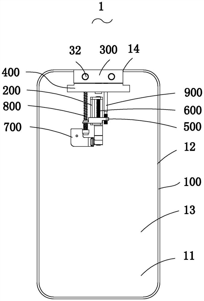
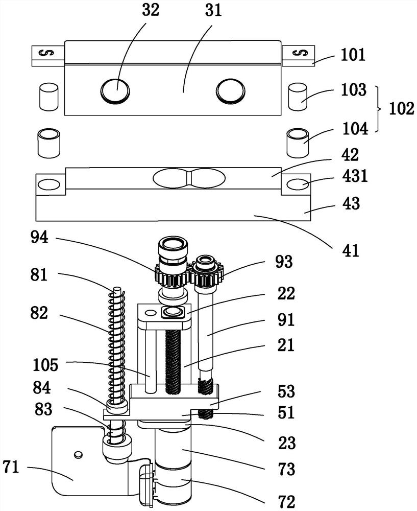
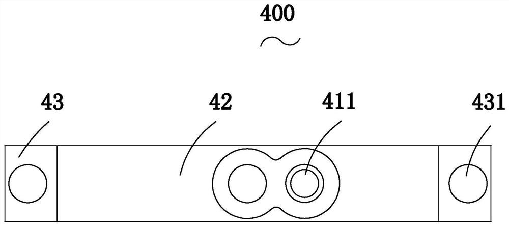
[0075]according toFigure 1-11As shown, the embodiment of the present invention provides an electronic device 1, and the electronic device 1 can be any of a mobile phone, a flat plate, ...


PUM


Abstract

The invention provides an electronic device and a method of use. The electronic device includes a back shell, a lens module, a support, a push block, a screw, a driving mechanism, a first transmission component, a second transmission component for driving the rotation of the lens module, The magnetic part and the electromagnet, the support part and the lens module are connected in rotation, the push block is sleeved on the screw rod and can move along the axial direction of the screw rod, the push block is threadedly matched with the screw rod, the driving mechanism is installed on the back shell, and is connected with the screw rod Rod connection, the first transmission assembly includes a first guide rod, a first elastic member, a second elastic member and a bushing assembly, the bushing assembly includes a bushing body, a bushing seat and a bushing cover, one end of the first guiding rod is connected to the support The first guide rod is slidably connected with the push block through the bush assembly, the first elastic part is compressed between the support part and the bush seat, the second elastic part is compressed between the push block and the bush cover, and the magnetic part The two electromagnets are opposite to each other, and one is arranged on the surrounding wall, and the other is arranged on the stopper. The lens module can be stretched and rotated bidirectionally.

Description

[Technical field][0001]The present invention relates to the field of imaging techniques, and more particularly to an electronic device and method of use with an imaging adjustment device.【Background technique】[0002]The current electronic device is usually utilizing the driving mechanism to provide power and the lens lifting, rotating to any location, the rear photographing, 360 degrees and scans, etc., the application scenario is widely used, but the structure Limit, the lens can only perform one-way rotation, constrained the application scenario of the lens, but also affects the user's experience.[0003]It is therefore necessary to develop an electronic device that overcomes the above problems.[Summary][0004]A first object of the present invention is to provide an electronic device, and its lens module has an advantage of scalable and bidirectional rotation.[0005]The technical solutions of the present invention are as follows:[0006]An electronic device, including:[0007]Lens module;[...

Claims


Application Information

Patent Timeline
Patent Type & Authority Patents(China)
IPC IPC(8): H04M1/02
CPCH04M1/026H04M1/0264
Inventor 周帅宇王尧刘柯佳吴龙兴
Owner AAC OPTICS (CHANGZHOU) CO LTD
Why Eureka
Try Eureka