Swing type bidirectional positioning clutch

A two-way positioning and clutch technology, applied in the field of clutches, achieves the effects of good product consistency, simple structure, and small size

Inactive Publication Date: 2014-08-20
WUXI KAIXUAN MOTOR
View PDF5 Cites 0 Cited by
  • Summary
  • Abstract
  • Description
  • Claims
  • Application Information

AI Technical Summary

Problems solved by technology

[0003] The purpose of the present invention is to provide a swing type two-way positioning clutch, which has the characteristics of simple structure, small size, convenient assembly, flexible operation and low production cost, so as to solve the problems existing in the two-way clutch in the prior art

Method used


Image

  • Swing type bidirectional positioning clutch
  • Swing type bidirectional positioning clutch
  • Swing type bidirectional positioning clutch

Examples


Embodiment Construction

[0016] The technical solutions of the present invention will be further described below in conjunction with the accompanying drawings and through specific implementation methods.

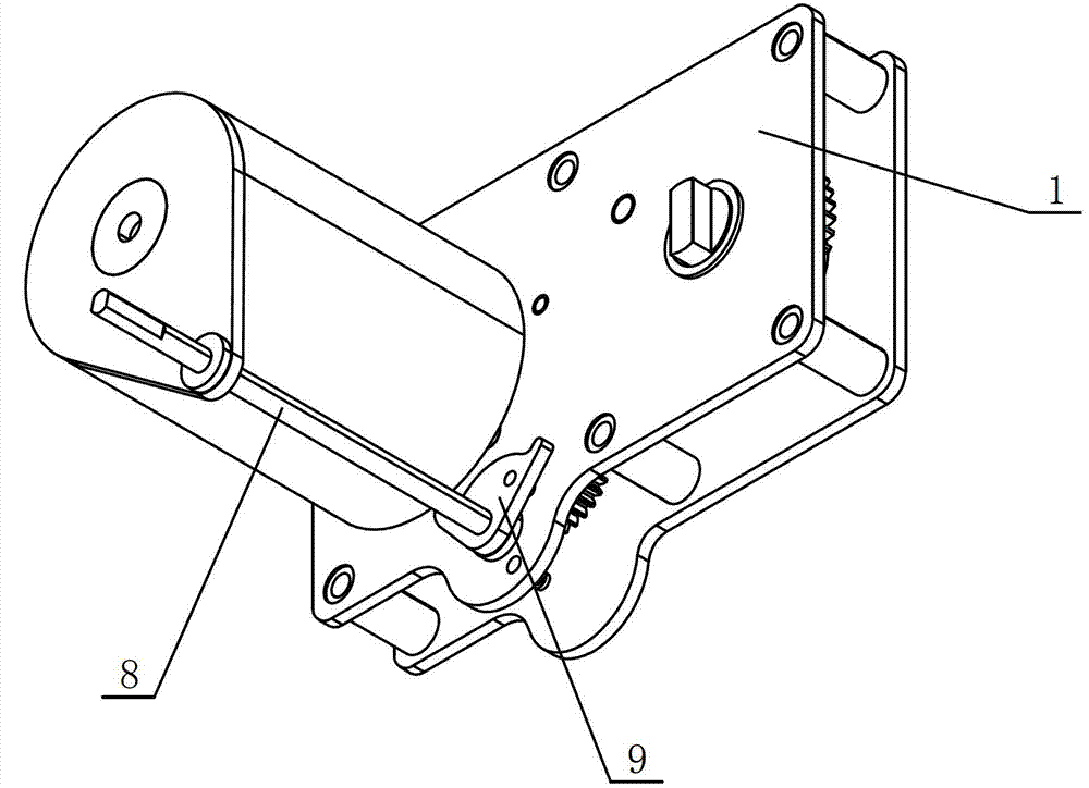
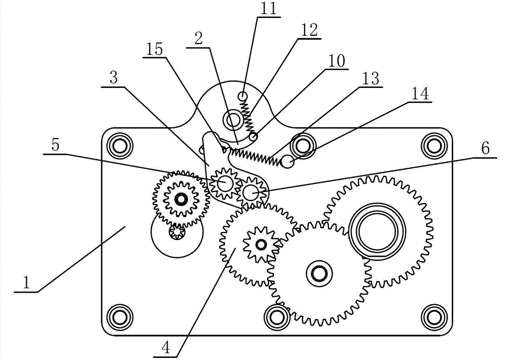
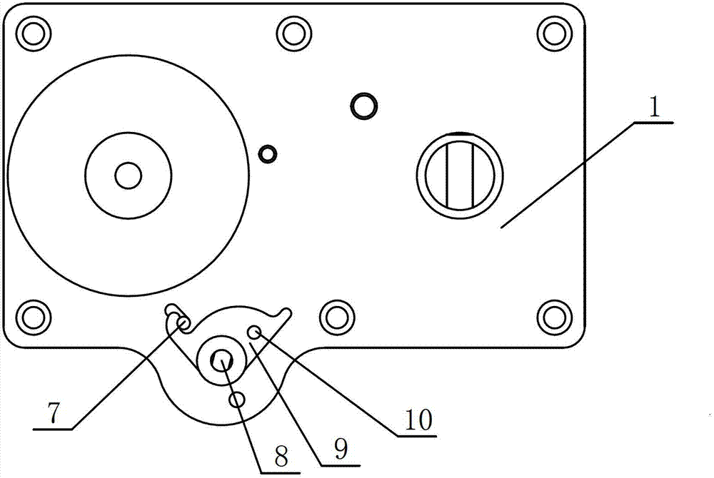
[0017] see Figure 1 to Figure 3 As shown, in this embodiment, a swing type two-way positioning clutch includes a box body 1 and a reduction gear assembly assembled on the box body 1, and a section of arc-shaped chute 2 is opened on the side wall of the box body 1 , and the inner side of the box body 1 is rotatably installed with a rocking plate 3, and a driving gear 5 and a swing gear 6 which mesh with each other are installed on one side of the rocking plate 3, and the swing gear 6 can be optionally combined with a reduction gear assembly The driven gear 4 is disengaged or meshed. The other side of the rocking plate 3 is fixedly connected with the locking pin 7, and the outer side of the box body 1 is rotatably provided with a rocker 8, and the two-way limit cams with card slots at both ends are ...


PUM


Abstract

The invention discloses a swing type bidirectional positioning clutch which comprises a box body and a reduction gear component which is assembled on the box body, wherein a section of arc chute is arranged on the box body; a rocker panel is rotationally arranged at the inner side of the box body; a clutch gear component is arranged on one side face of the rocker panel; a clamping pin is arranged on the other side face of the rocker panel; a rocking bar is rotationally arranged at the outer side of the box body; a bidirectional limiting cam plate is fixedly connected to the rocking bar, wherein the two ends of the rocking bar are provided with clamping grooves; one end of a first positioning pin is fixed on the bidirectional limiting cam plate; the other end of the first positioning pin is clamped in the chute; a positioning spring is arranged between the first positioning pin and a second positioning pin; a reset part is arranged between the rocker panel and the box body; and the clamping pin penetrates through the chute and is pressed against a cam surface of the bidirectional limiting cam plate. The bidirectional positioning clutch has the advantages of simple structure, small size, convenient assembly, flexible operation and low production cost.

Description

technical field [0001] The invention relates to a clutch, in particular to a swing type two-way positioning clutch used in a speed reduction mechanism. Background technique [0002] At present, with the continuous development of the machinery industry, various forms of deceleration mechanisms are gradually developing towards miniaturization in the design process. Two-way clutches are more and more widely used in deceleration mechanisms. Traditional two-way clutches have complex structures and cumbersome assembly. The production cost is high, and it is difficult to meet the trend of miniaturization of the reduction mechanism. Contents of the invention [0003] The purpose of the present invention is to provide a swing type two-way positioning clutch, which has the characteristics of simple structure, small size, convenient assembly, flexible operation and low production cost, so as to solve the problems existing in the two-way clutch in the prior art. [0004] For reaching...

Claims


Application Information

Patent Timeline
Patent Type & Authority Patents(China)
IPC IPC(8): F16D11/00F16H37/12
Inventor 吴传渠
Owner WUXI KAIXUAN MOTOR
Why Eureka
Try Eureka