Pillar structure for vehicle

A technology for pillars and vehicles, which is applied to vehicle parts, superstructures, subassemblies of superstructures, etc., to achieve the effect of saving assembly space and promoting narrow width

Inactive Publication Date: 2020-05-19
TOYOTA JIDOSHA KK
7 Cites 0 Cited by

AI-Extracted Technical Summary

Problems solved by technology

[0003] However, in order to narrow the width of the front pillar, in addition to finding a way to the structure (shape) of the pillar decoration itself, it is also po...

Method used

[0062] That is, the overlapping portion 37 and the wire bonding portion 38 of the inner flange portion 32B and the inner flange portion 34B, and the through hole 35A serving as a portion for assembling the clip 66 are provided on the same flat side. Therefore, in the case where the inner flange portion 32B does not overlap with the inner flange portion 34B and the through hole 35A is not formed in the inner flange portion 34B (a through hole for assembly is formed outside the inner flange portion 34B and the inner flange portion 32B). When viewed from the longitudinal direction of the A-pillar 20, the distance between the wire bonding portion 38 and the through-hole 35A in the direction perpendicular to the longitudinal direction can be reduced compared to the case of a hole).
[0064] In addition, since the front pillar garnish 60 is formed in a substantially U-shape opening toward the vehicle outer side in a top cross-sectional view, it can also The width of the front pillar garnish 60 itself is narrowed. Accordingly, it is possible to further narrow the width of the A-pillar 20 .
[0065] In addition, the wire bonding portions 38 are intermittently formed, and the through holes 35A are formed between the wire bonding portions 38. Therefore, compared with the case where the through hole 35A is not formed between the intermittently formed wire bonding portions 38 , the wire bonding portion 38 in the direction perpendicular to the longitudinal direction of the A-pillar 20 can be reduced in size. The distance from the through hole 35A. Accordingly, narrowing of the front pillar 30 can be promoted.
[0066] Furthermore, the inner flange portion 34B between the wire bonding portions 38 is formed with an extension portion 35 extending from the edge portion 34C, and the extension portion 35 is formed with a through hole 35A. Therefore, compared with the case where the edge portion 34C of the inner flange portion 34B between the wire-welded portions 38 is not formed with the protruding portion 35 , the wire-welding in the direction perpendicular to the longitudinal dir...

Abstract

There is provided a pillar structure for a vehicle, that has: a pillar frame member having a superposed portion, at which a second wall portion, which faces a vehicle cabin side, of a second member that extends in a length direction of a pillar is superposed with a first wall portion, which faces the vehicle cabin side, of a first member that extends in the length direction of the pillar, and linearly welded portions that are formed due to an edge end portion of the second wall portion being linearly welded to the first wall portion; and a pillar garnish that is mounted at least to the secondwall portion, and covers the first wall portion and the second wall portion from the vehicle cabin side.

Application Domain

Superstructure subunits

Technology Topic

Aerospace engineeringStructural engineering +1

Image

  • Pillar structure for vehicle
  • Pillar structure for vehicle
  • Pillar structure for vehicle

Examples

  • Experimental program(1)

Example Embodiment

[0025] Hereinafter, embodiments of the present invention will be described in detail based on the drawings. It should be noted that, for convenience of description, the arrow UP appropriately shown in each figure is set as the vehicle up direction, the arrow FR is set as the vehicle front direction, and the arrow RH is set as the vehicle right direction. Therefore, in the following description, when the directions of up and down, front and back, and left and right are described without special description, they indicate up and down in the vehicle up and down direction, front and back in the vehicle front and rear direction, and left and right in the vehicle left and right direction (vehicle width direction).
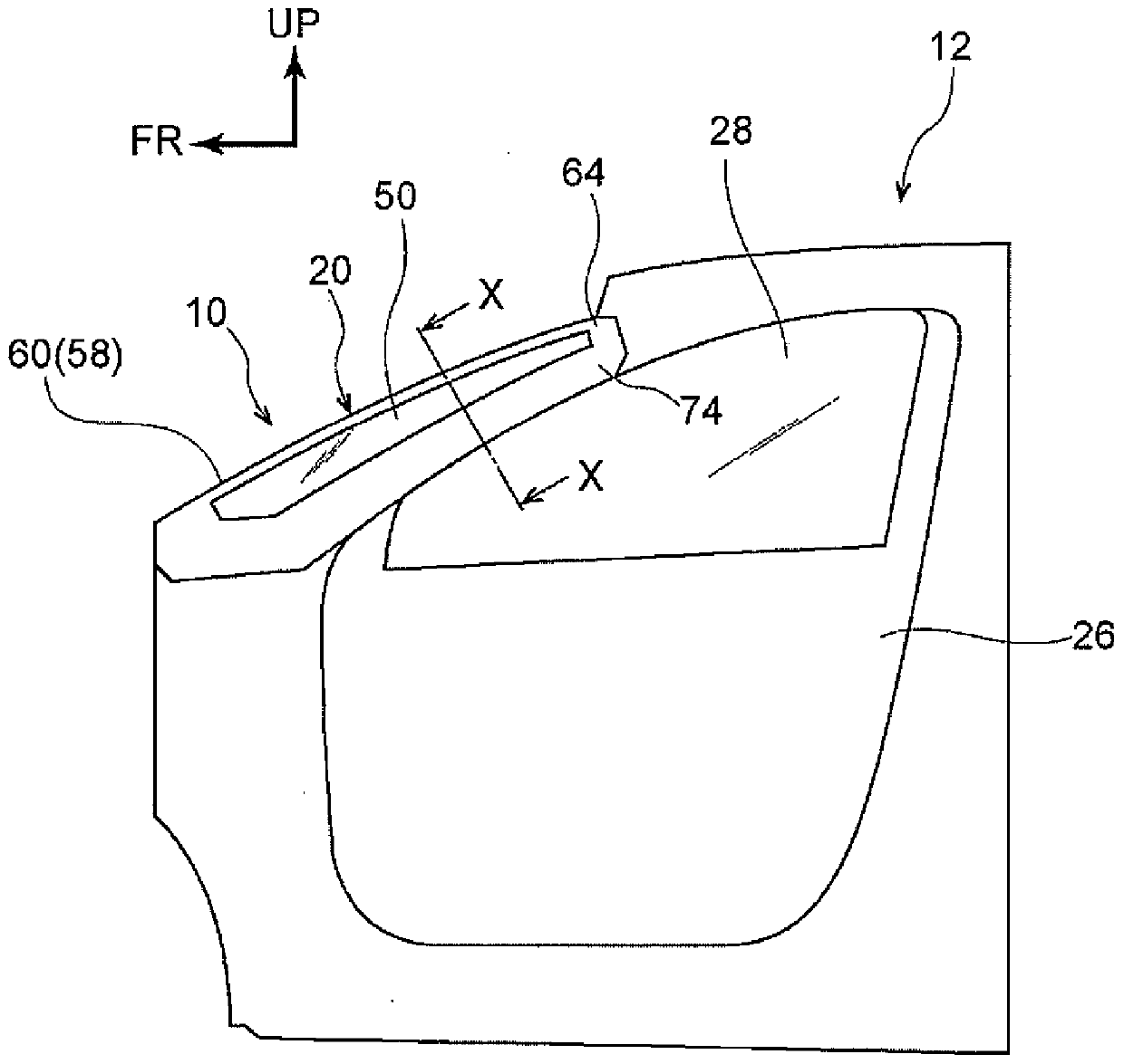
[0026] Such as figure 2 As shown, the vehicle 12 is provided with a windshield (hereinafter referred to as "front glass") 18 that is inclined to the rear of the vehicle as it goes to the upper side of the vehicle and separates the inner side of the cabin 14 from the outer side of the cabin 14 . And like figure 1 As shown, a pair of left and right front pillars to which the vehicle pillar structure 10 of the present embodiment is applied is provided on the vehicle front side of the front window 28 in the front door 26 on the outer side of the front glass 18 in the vehicle width direction (hereinafter referred to as " A column") 20.
[0027] A pair of left and right A pillars 20 are respectively along the vehicle width direction outer end 18A of the front glass 18 (refer to figure 2 ) And extend substantially in the vertical direction of the vehicle as the longitudinal direction. That is, the pair of left and right A-pillars 20 respectively incline to the rear side of the vehicle as they go to the upper side of the vehicle. It should be noted that the left side (for example, the passenger seat side) and the right side (for example, the driver seat side) of the A-pillar 20 are bilaterally symmetrical and have the same structure. Therefore, the right A-pillar 20 will be described below.
[0028] Such as figure 2 As shown, the A-pillar 20 has a front pillar 30 as a front pillar frame member and a rear pillar 40 as a rear pillar frame member. The front pillar 30 extends substantially along the vertical direction of the vehicle, such as image 3 As shown, the vehicle width direction outer end 18A of the front glass 18 is joined to the front pillar 30 via a urethane adhesive 52 and a cushion rubber 54.
[0029] In addition, the front pillar 30 is configured to include a front pillar outer plate 32 made of a steel plate as a first member and a front pillar inner plate 34 made of a steel plate as a second member. The front pillar outer panel 32 has a cross-sectional shape orthogonal to the longitudinal direction (extending direction along substantially the vertical direction of the vehicle) into a substantially "C" shape. The cross-sectional shape perpendicular to the vertical direction (extending direction) is formed into a substantially "S" shape. It should be noted that a ridge portion (corner portion) 34D along the longitudinal direction is formed on the vehicle rear side of the front pillar inner panel 34.
[0030] In addition, the front pillar outer panel 32 and the front pillar inner panel 34 form a closed cross-sectional shape. That is, the front pillar inner panel 34 is provided substantially opposite to the vehicle rear side of the front pillar outer panel 32, and the front pillar outer panel 32 and the front pillar inner panel 34 are joined by spot welding and wire welding.
[0031] In detail, the outer flange portion 32A, which is the vehicle width direction outer end of the front pillar outer panel 32, and the outer flange portion 34A, which is the vehicle width direction outer end portion of the front pillar inner panel 34, overlap each other. Part is spot welded. In other words, a plurality of spot welds 36 are formed (intermittently) in the outer flange portion 32A and the outer flange portion 34A at a predetermined interval in the longitudinal direction.
[0032] On the other hand, such as image 3 , Figure 4 Shown are the inner end of the front pillar outer panel 32 in the vehicle width direction and are the inner flange portion 32B of the first wall portion facing the side of the cabin 14 and the vehicle width direction inner end of the front pillar inner panel 34 In addition, the inner flange portions 34B of the second wall portion facing the vehicle interior 14 side overlap each other, and the overlapped portion is referred to as the overlap portion 37.
[0033] In addition, the edge portion 34C of the inner flange portion 34B is linearly welded to the inner flange portion 32B. That is, a plurality of wire bonding portions 38 are formed (intermittently) in the inner flange portion 32B and the inner flange portion 34B at predetermined intervals in the longitudinal direction. In addition, as a means for welding the inner flange portion 32B and the inner flange portion 34B in a linear shape, arc welding, laser welding, and the like can be cited.
[0034] Such as figure 2 As shown, the rear pillar 40 is arranged on the substantially vehicle rear side of the front pillar 30. In other words, the rear pillar 40 is arranged at a predetermined interval with respect to the front pillar 30 substantially in the longitudinal direction of the vehicle, and extends substantially parallel to the front pillar 30 (along the substantially vertical direction of the vehicle).
[0035] The rear pillar 40 is configured to include a rear pillar outer panel 42 made of steel sheet, a rear pillar reinforcement 43 made of steel sheet, and a rear pillar inner panel 44 made of steel sheet. The rear pillar outer panel 42 and the rear pillar reinforcement 43 are formed into a substantially flat plate shape, and the cross-sectional shape of the rear pillar inner panel 44 perpendicular to the longitudinal direction (extending direction along the vehicle vertical direction) is formed into a substantially bowler hat shape. shape.
[0036] In addition, the rear pillar outer panel 42, the rear pillar reinforcement 43, and the rear pillar inner panel 44 form a closed cross-sectional shape. That is, a rear pillar reinforcement 43 and a rear pillar inner panel 44 are provided on the inner side of the rear pillar outer panel 42 in the approximate vehicle width direction, and the rear pillar outer panel 42, the rear pillar reinforcement 43 and The rear pillar inner plate 44 is joined by spot welding.
[0037] In detail, the vehicle front end of the rear pillar outer panel 42 is the front flange portion 42A, the vehicle front end of the rear pillar reinforcement 43 is the front flange portion 43A, and the rear pillar inner panel The front flange portion 44A, which is the vehicle front side end portion of 44, overlaps each other, and the overlapped portion is spot welded. That is, a plurality of spot welds 46 are formed in the front flange portion 42A, the front flange portion 43A, and the front flange portion 44A at predetermined intervals in the longitudinal direction.
[0038] In addition, the vehicle rear end of the rear pillar outer panel 42 that is the rear flange portion 42B, the vehicle rear end of the rear pillar reinforcement 43 that is the rear flange portion 43B and the rear pillar inner panel 44 The rear side end portions, that is, the rear side flange portion 44B overlap each other, and the overlapped portion is spot welded.
[0039] That is, the rear flange portion 42B, the rear flange portion 43B, and the rear flange portion 44B are also formed with a plurality of spot welding portions 48 at predetermined intervals in the longitudinal direction thereof. It should be noted that the rear flange portion 42B, the rear flange portion 43B, and the rear flange portion 44B that overlap each other are fitted with a resin (rubber) opening weather strip by fitting from substantially the rear of the vehicle twenty two.
[0040] In addition, an A-pillar glass 50 as a transparent member is bridged between the front pillar 30 and the rear pillar 40 via pillar glass molds 56, 57, cushion rubber 54 and urethane adhesive 52 described later. It should be noted that the A-pillar glass 50 is a transparent window member with a substantially vehicle width direction as the plate thickness direction, and when viewed from the side, it is inclined toward the rear side of the vehicle as it goes to the upper side of the vehicle (refer to figure 1 ).
[0041] Such as image 3 As shown, the front end of the A-pillar glass 50 is integrally mounted with a resin (rubber) pillar glass mold 56 having a substantially right-angled triangle shape in plan view and a right-angled portion arranged on the vehicle width direction inner side and the vehicle rear side. In addition, positioning protrusions 56B are integrally formed on the left and right sides of the wall surface 56A facing the vehicle compartment 14 side of the pillar glass mold 56, and a polyurethane adhesive 52 is installed between the protrusions 56B.
[0042] Such as figure 2 As shown, the rear end of the A-pillar glass 50 is integrally mounted with a resin (rubber) pillar glass mold 57 having a substantially right-angled triangle shape in plan view and a right-angled portion arranged on the outside in the vehicle width direction and on the rear side of the vehicle. Furthermore, a urethane adhesive 52 is attached to the vehicle rear side of the wall surface 57A facing the vehicle compartment 14 side of the pillar glass mold 57, and a cushion rubber 54 is attached to the vehicle front side of the wall surface 57A.
[0043] Therefore, the front end portion of the A-pillar glass 50 is positioned from the front side of the vehicle by the protruding portion 56B via the pillar glass mold 56 and joined to the outer flange portion 32A by the urethane adhesive 52 to be attached to the front pillar 30. In addition, the rear end portion of the A-pillar glass 50 is positioned from the outer side in the vehicle width direction by the cushion rubber 54 through the pillar glass mold 57 and joined to the front flange 42A by the urethane adhesive 52 to be attached to the rear pillar 40.
[0044] In addition, such as figure 2 , image 3 As shown, the outer end 18A of the front glass 18 in the vehicle width direction is fitted from the outer side in the vehicle width direction to provide a resin (rubber) molding 16 as a sealing member. The outer end 16A in the vehicle width direction of the mold 16 abuts against the pillar glass mold 56 in an elastically deformed state (predetermined pressure). That is, the mold 16 provided between the outer end 18A of the front glass 18 in the vehicle width direction and the pillar glass mold 56 prevents rainwater from entering between the A pillar glass 50 and the front glass 18.
[0045] In addition, such as figure 2 As shown, the door frame 24 of the front door 26 is arranged on the outer side of the rear pillar outer panel 42 in the vehicle width direction. A door weather strip 23 is provided on the vehicle front side of the door frame 24, and a glass run 25 is provided on the vehicle rear side of the door frame 24. It should be noted that the A-pillar glass 50 is not limited to glass, and may be made of, for example, transparent fiber-reinforced resin.
[0046] Such as figure 2 , image 3 As shown, an A-pillar garnish 58 is provided on the inner side of the front pillar 30 and the rear pillar 40 in the vehicle width direction. The A-pillar garnish 58 is made of resin, and is configured to include a front pillar garnish 60 provided on the side of the vehicle cabin 14 of the front pillar 30 and a rear pillar garnish 70 provided on the side of the vehicle cabin 14 of the rear pillar 40.
[0047] The front pillar garnish 60 has a main body 62 extending substantially in the vertical direction of the vehicle along the front pillar 30 and an extension 64 integrally provided at the upper end of the main body 62 and extending substantially to the rear of the vehicle (see figure 1 ). The lower end of the main body 62 is inserted into an insertion port (not shown) formed in the dashboard (not shown), and the upper end of the extension 64 abuts against the roof liner (not shown).
[0048] Such as image 3 As shown, the main body portion 62 of the front pillar garnish 60 has a cross-sectional shape orthogonal to the longitudinal direction (in a plan cross-sectional view) formed into a substantially U-shape that opens toward the outer side of the vehicle width direction, and the front pillar 30 (front side The inner flange portion 32B of the pillar outer panel 32 and the inner flange portion 34B and the outer flange portions 32A, 34A of the front pillar inner panel 34 are covered in a non-contact state from the vehicle compartment 14 side.
[0049] It should be noted that in image 3 In the top cross-sectional view shown, the rear side wall portion 62B of the main body 62 facing the front pillar inner plate 34 is formed longer than the front side wall portion 62A facing the front pillar outer plate 32. The tip portion 62C of the side wall portion 62B is slightly bent toward the front side of the vehicle.
[0050] That is, the front end portion 62C of the side wall portion 62B is arranged so as to approach the outer flange portion 32A and the outer flange portion 34A. Thus, as Figure 5 As shown, the blind spot Dw caused by the front pillar garnish 60 when viewed from the driver's seat is less than the distance between the pupil centers, and the front pillar garnish 60 when viewed from the front passenger seat The blind angle Pw caused is also a structure below the distance between pupil centers.
[0051] It should be noted that the "distance between pupil centers" refers to the distance between the pupil center of the right eye and the pupil center of the left eye of the driver sitting in a seat (not shown), for example, in Japanese adults It is set to about 60 to 65 mm. In this embodiment, as an example, the distance between the centers of the pupils is set to "65 mm".
[0052] In addition, a plurality of substantially arrow-shaped clips 66 having an enlarged diameter portion 68 on the distal end side are provided on the inner surface of the main body portion 62 at a predetermined interval along the longitudinal direction of the main body portion 62. The clip 66 (the enlarged diameter portion 68) as a locking member is formed to be elastically deformable in a direction orthogonal to the direction in which it protrudes so as to be able to interact with the inner flange portion 34B of the front pillar inner panel 34 and the front pillar outer panel 32 The inner flange portion 32B is protrudingly provided on the inner surface (wall surface) of the main body portion 62 so as to face each other.
[0053] In addition, such as Figure 4 As shown, the inner flange portion 34B of the front pillar inner plate 34 is formed with an extension portion 35 projecting from the edge end portion 34C to the substantially vehicle front side, and a rectangular through hole 35A is formed in the extension portion 35 . In addition, the inner flange portion 32B of the front pillar outer plate 32 is not formed with a through hole communicating with the through hole 35A, but is formed with a cutout portion 33 cut off substantially along the shape of the extension portion 35.
[0054] In addition, the through hole 35A is formed between the wire bonding portions 38, and is formed on the virtual extension line K connecting the wire bonding portions 38 (the virtual extension line K passes through the center of the through hole 35A). In addition, the inner diameter of the through hole 35A is formed to be slightly smaller than the outer diameter of the enlarged diameter portion 68. Therefore, the front pillar garnish 60 is inserted into the through hole 35A while being elastically deformed by the enlarged diameter portion 68 of the clip 66, and then the enlarged diameter portion 68 is restored to be attached to the front pillar 30.
[0055] Such as figure 2 As shown, the rear pillar garnish 70 has a main body 72 extending substantially in the vertical direction of the vehicle along the rear pillar 40 and an extension 74 integrally provided at the upper end of the main body 72 and extending substantially to the rear of the vehicle. Reference figure 1 ). The lower end of the main body 72 is inserted into an insertion port formed in the dashboard similarly to the front pillar trim 60, and the upper end of the extension 74 abuts against the roof lining.
[0056] The cross-sectional shape of the main body 72 of the rear pillar garnish 70 perpendicular to the longitudinal direction (in a plan cross-sectional view) is formed into a substantially U-shaped opening toward the outer side of the vehicle width direction, and the rear pillar 40 is formed from the side of the cabin 14 Non-contact state coverage. It should be noted that in figure 2 In the illustrated plan cross-sectional view, the front side wall portion 72A of the main body portion 72 facing the rear pillar inner plate 44 is formed to be longer than the rear side wall portion 72B.
[0057] In addition, a plurality of substantially arrow-shaped clips 76 having an enlarged diameter portion 78 on the distal end side are provided on the inner surface of the rear pillar garnish 70 along the longitudinal direction of the main body portion 72 at predetermined intervals. The clip 76 (the enlarged diameter portion 78) is also formed to be elastically deformable in a direction orthogonal to the direction in which it protrudes, and is protrudingly provided on the main body so as to be able to oppose the support portion 45 integrally provided on the rear pillar inner plate 44 The inner surface (wall surface) of the portion 72.
[0058] In addition, a rectangular through hole (not shown in the figure) that is slightly smaller than the outer diameter of the enlarged diameter portion 78 is formed in the support portion 45 integrally provided on the rear pillar inner plate 44. Therefore, the rear pillar garnish 70 is inserted into the through hole while being elastically deformed by the enlarged diameter portion 78 of the clip 76, and then the enlarged diameter portion 78 is restored to be attached to the rear pillar 40.
[0059] In the vehicle pillar structure 10 of the present embodiment configured as described above, its function will be described next.
[0060] Such as image 3 , Figure 4 As shown, a flat overlapping portion 37 is formed by overlapping the inner flange portion 34B of the front pillar inner plate 34 on the inner flange portion 32B of the front pillar outer plate 32. In addition, the wire welded portion 38 is formed by linearly welding the edge end portion 34C of the inner flange portion 34B to the inner flange portion 32B.
[0061] In addition, the front pillar garnish 60 covering the front pillar 30 (inner flange portions 32B, 34B and outer flange portions 32A, 34A) from the side of the vehicle compartment 14 is formed in a substantially U-shaped opening to the outside of the vehicle in a plan cross-sectional view. shape. In addition, the clip 66 protrudingly provided on the inner surface of the main body portion 62 of the front pillar garnish 60 is inserted into the through hole 35A formed in the inner flange portion 34B to be attached to the front pillar 30.
[0062] That is, the overlapping portion 37 and the wire welding portion 38 of the inner flange portion 32B and the inner flange portion 34B, and the through hole 35A as a portion where the clip 66 is assembled are provided on the same flat surface side. Therefore, it does not overlap with the inner flange portion 32B and the inner flange portion 34B, and the through hole 35A is not formed in the inner flange portion 34B (the inner flange portion 34B and the inner flange portion 32B are formed with a through hole for assembly other than Compared with the case of a hole, when viewed from the longitudinal direction of the A-pillar 20, the distance between the wire bonding portion 38 and the through hole 35A in a direction orthogonal to the longitudinal direction can be reduced.
[0063] Thereby, the efficiency (space saving) of the assembly space of the front pillar garnish 60 in the front pillar 30 can be achieved, and the width of the front pillar 30 can be reduced. That is, as a result, the width of the A-pillar 20 can be narrowed, and the blind spot Dw caused by the front pillar garnish 60 when viewed from the driver's seat side and the front pillar garnish when viewed from the passenger seat side can be reduced The blind angle Pw caused by 60 is reduced well (becomes less than the distance between pupil centers).
[0064] In addition, since the front pillar garnish 60 is formed in a substantially U-shape that opens to the outside of the vehicle in a plan cross-sectional view, the front side can also be obtained compared to a case where it is not formed into the substantially U-shape that opens to the outside of the vehicle. The pillar garnish 60 itself is narrowed. In this way, the width of the A-pillar 20 can be further narrowed.
[0065] In addition, the wire bonding portions 38 are formed intermittently, and the through holes 35A are formed between the wire bonding portions 38. Therefore, compared with the case where the through-hole 35A is not formed between the intermittently formed wire bonding portions 38, the wire bonding portion 38 in the direction orthogonal to the longitudinal direction of the A-pillar 20 can be reduced. The distance from the through hole 35A. This can promote the narrowing of the front pillar 30.
[0066] In addition, the inner flange portion 34B between the wire welding portions 38 is formed with a projecting portion 35 projecting from the edge end portion 34C, and a through hole 35A is formed in the projecting portion 35. Therefore, compared with the case where the edge end portion 34C of the inner flange portion 34B between the wire welding portions 38 is not formed with the overhanging portion 35, the wire welding in the direction orthogonal to the longitudinal direction of the A-pillar 20 can be further reduced. The distance between the portion 38 and the through hole 35A.
[0067] In addition, the through hole 35A is formed on the virtual extension line K connecting the wire bonding portions 38 to each other. Therefore, compared with the case where the through hole 35A is formed at a position offset from the virtual extension line K connecting the wire bonding portions 38 to each other, the wire bonding portion 38 in the direction orthogonal to the longitudinal direction of the A pillar 20 can be further reduced. The distance from the through hole 35A. This can further promote the narrowing of the front pillar 30.
[0068] In addition, when a load is applied to the A pillar 20 from the front side of the vehicle, the front pillar 30 is bent and deformed toward the rear side of the vehicle. which is, Figure 5 The vehicle front side of the central axis CL indicated by the one-dot chain line is tensile deformed (set to the tensile deformation Td side), and the vehicle rear side is compressively deformed (set to the compressive deformation Cd side).
[0069] However, as Figure 5 As shown, a ridge portion 34D extending in the longitudinal direction of the front pillar inner plate 34 is arranged on the rear side of the front pillar 30 that is the side of the compression deformation Cd. Therefore, the rear part of the front pillar 30 has resistance to compression deformation. This can suppress its compression deformation.
[0070] In addition, although the outer flange portion 32A and the outer flange portion 34A are joined by spot welding, the outer flange portion 32A and the outer flange portion 34A are formed so as to protrude outward in the vehicle width direction, so that it can be easily inserted. Welding gun 80 (reference Figure 5 )Space. Thereby, the joining of the outer flange portion 32A and the outer flange portion 34A can be easily performed.
[0071] In addition, although the inner flange portion 32B and the inner flange portion 34B are linearly welded (the structure having the wire welded portion 38), the outer flange portion 32A and the outer flange portion 34A are joined by spot welding (with The structure of the spot welding portion 36). Therefore, compared with a case where the outer flange portion 32A and the outer flange portion 34A are welded linearly, the amount of heat input to the front pillar 30 can be reduced. Thus, in the front pillar 30, it is possible to suppress or prevent the occurrence of thermal strain.
[0072] In addition, the A-pillar 20 of this embodiment includes transparent A-pillar glass 50. Therefore, the driver (occupant) can visually confirm the condition of the outside of the A-pillar 20 through the A-pillar glass 50 from between the front pillar garnish 60 (front pillar 30) and the rear pillar garnish 70 (rear pillar 40) .
[0073] It should be noted that such as Image 6 As shown, in the front pillar 30, the outer flange portion 32A of the front pillar outer plate 32 and the outer flange portion 34A of the front pillar inner plate 34 may be welded linearly by arc welding, laser welding, etc. . That is, the outer flange portion 32A and the outer flange portion 34A may be joined at a plurality of wire welding portions 38.
[0074] In this case, the closed cross-sectional shape of the front pillar 30 can be image 3 The shown closed cross-sectional shape of the front pillar 30 is large, and therefore has an advantage that the rigidity of the front pillar 30 can be improved. However, in this case, as described above, since the amount of heat input to the front pillar 30 increases, there is also a disadvantage that thermal strain is likely to occur in the front pillar 30.
[0075] As mentioned above, although the vehicle pillar structure 10 of the present embodiment has been described based on the drawings, the vehicle pillar structure 10 of the present embodiment is not limited to the illustrated structure, and can be appropriately implemented within the scope not departing from the spirit of the present invention. Design changes. For example, the inner flange portion 32B may not be formed with the cutout portion 33, but a through hole (not shown) communicating with the through hole 35A may be formed.

PUM

no PUM

Description & Claims & Application Information

We can also present the details of the Description, Claims and Application information to help users get a comprehensive understanding of the technical details of the patent, such as background art, summary of invention, brief description of drawings, description of embodiments, and other original content. On the other hand, users can also determine the specific scope of protection of the technology through the list of claims; as well as understand the changes in the life cycle of the technology with the presentation of the patent timeline. Login to view more.
Why Eureka
Try Eureka