
Card connector

A technology for card connectors and cards, which is applied in the direction of connection, parts of connection devices, instruments, etc. It can solve the problems of narrow card insertion opening, no provision, and inability to prevent deformation of the side sensing arm, so as to prevent card insertion operability The effect of reducing, promoting narrow width and thinning

Inactive Publication Date: 2004-04-28
HOSIDEN CORP
View PDF0 Cites 0 Cited by
  • Summary
  • Abstract
  • Description
  • Claims
  • Application Information

AI Technical Summary

Problems solved by technology

Therefore, as described in this patent document 1, it is difficult to promote the thinning of the connector housing with the technique of reinforcing the side sensor arm by inserting the retaining tab of the reinforcement plate into the opening formed on the side sensor arm. Shape and Narrow
And this patent document 1 also records that the above-mentioned rectangular piece at the top end of the reinforcing plate is inserted in the groove formed near the top end of the side sensing arm. The partial deformation of the above-mentioned insertion part cannot prevent the deformation of the front end of the side sensor arm, not to mention that it is difficult to promote the thinner shape of the connector shell because the slot for the above-mentioned rectangular piece insertion needs to be formed on the side sensor arm. The problem of scaling and narrowing cannot be solved
[0007] On the other hand, the technique described in Patent Document 2 is merely to integrally mold the reinforcing plate and the side arms with synthetic resin. The card gradually stretches the central part of the reinforcement plate in the width direction so that the card can be inserted. However, the problem that the left and right side arms are deformed inward and the card insertion opening is too narrow has not been solved.
[0008] As mentioned above, Patent Document 1 only provides the technology of using reinforcement plates to reinforce the left and right side sensing arms. Similarly, the reinforcement plates described in Document 2 only provide the technology of reinforcing the left and right side arms, and do not provide the technology for passing through. The basis of the design is to prevent the deformation of the left and right arms, and to realize the card insertion operability and the technology of narrowing and thinning the connector

Method used


Image

  • Card connector
  • Card connector
  • Card connector

Examples


Embodiment Construction

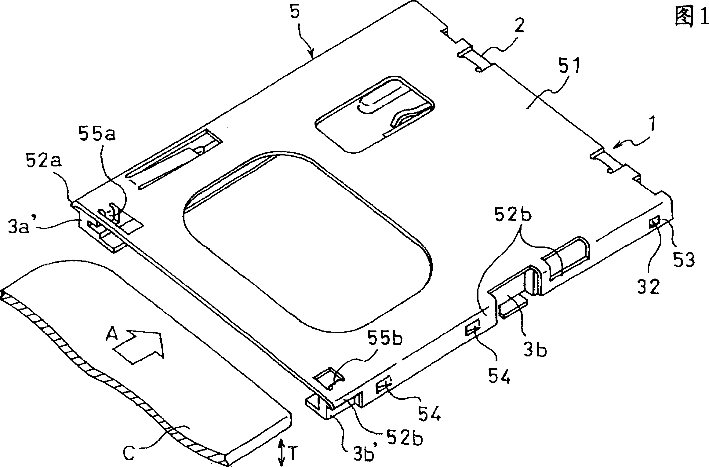
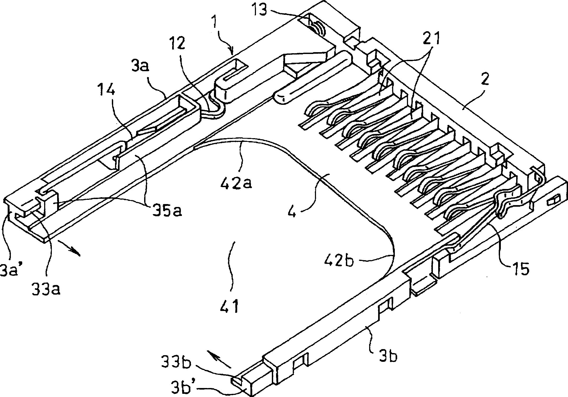
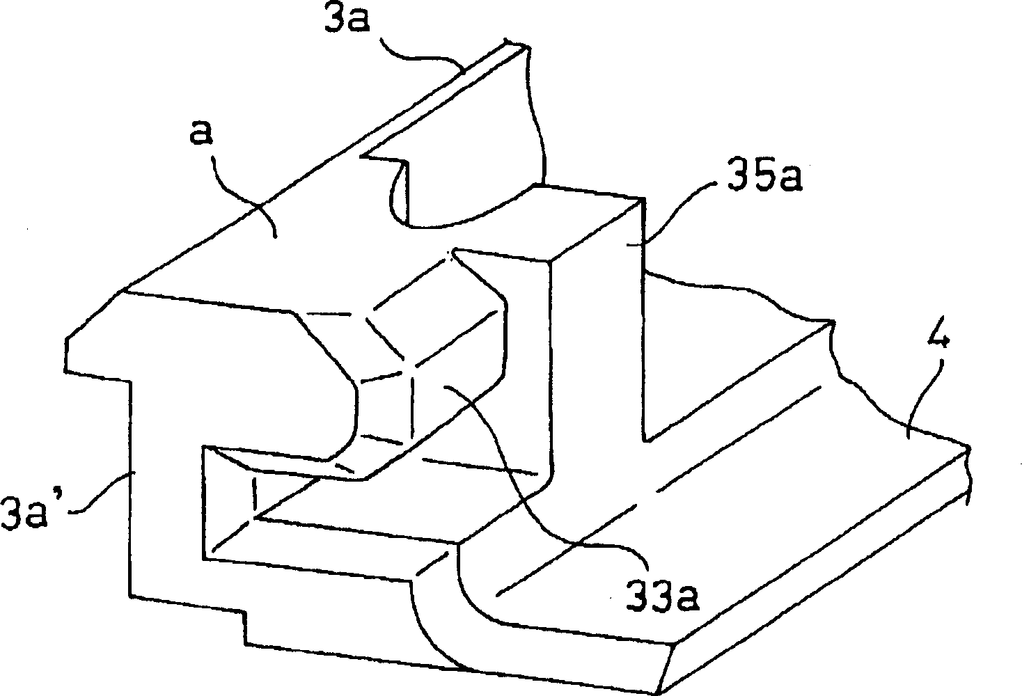
[0026] FIG. 1 is an external perspective view of a card connector according to an embodiment of the present invention. figure 2 It is an external perspective view of the main body 1. image 3 and Figure 4 It is an enlarged perspective view showing different parts of the main body 1 . Figure 5 It is an enlarged cross-sectional view showing a part of the important part omitted.

[0027] like figure 2 As shown, the main body 1 is an integral molding of synthetic resin, a pair of arms 3a, 3b extend from the left and right ends of the head 2 in the transverse direction, and has a lower plate connected to the head 2 and the pair of arms 3a, 3b Part 4, the head 2 is equipped with a column of contacts 21 arranged laterally with the required number of contacts. In addition, the lower plate portion 4 has a recessed portion 41 that is recessed toward the head 2 between the pair of arms 3a, 3b, and recessed corners 42a, 42b on the left and right sides of the recessed portion 41 are m...


PUM


Abstract

A card connector including a body made of an integral molded product of a synthetic resin, a head portion from which a pair of arms are extended, and a sheet metal frame. The arms have multipolar contacts. The sheet metal frame is stretched between the arms of the body, and cooperate with the body to form a card insertion space. The arms are prevented from being deformed, to adequately define the lateral width of a card insertion slot, whereby the operability of card insertion is maintained to a satisfactory level.

Description

technical field [0001] The present invention relates to a card connector, in particular, a card connector in which a card insertion space is formed by a body composed of a synthetic resin integral molding and a frame made of sheet metal attached to the body. Background technique [0002] In this kind of card connector, the body has a head with multiple contacts and a pair of left and right arms extending from the head. In an article that guides the card to be inserted through the left and right arms, if the left and right arms are deformed, from the initial If the design standard position of the card is shifted to the inside or outside, the operability of the card will be damaged, and sometimes the card cannot be inserted. In particular, if the left and right arms are deformed and shifted inward, even if the displacement of only one arm is small, the opening width (horizontal width of the card insertion port) becomes too narrow, and the operability of the card is damaged. ,...

Claims


Application Information

Patent Timeline
Patent Type & Authority Applications(China)
IPC IPC(8): G06K17/00G06K7/00G06K13/08H01R13/631H01R13/658H01R13/6599
CPCG06K13/08G06K7/0013H01R13/65805G06K7/0069H01R13/6599H01R12/71
Inventor 長田孝之
Owner HOSIDEN CORP
Features
  • Generate Ideas
  • Intellectual Property
  • Life Sciences
  • Materials
  • Tech Scout
  • Unparalleled Data Quality
  • Higher Quality Content
  • 60% Fewer Hallucinations
Learn More