Connector and plug thereof

A technology for plugs and plug housings, applied in connection, two-part connection devices, parts of connection devices, etc., can solve problems such as cumbersome operations, achieve simple unlocking methods, avoid large radial dimensions, and facilitate miniaturization Effect

Pending Publication Date: 2020-05-26
CHINA AVIATION OPTICAL-ELECTRICAL TECH CO LTD
View PDF1 Cites 5 Cited by
  • Summary
  • Abstract
  • Description
  • Claims
  • Application Information

AI Technical Summary

Problems solved by technology

[0004] The purpose of the present invention is to provide a plug to solve the problem that the plug connector in the prior art needs to use auxiliary devices to realize the separation of the plug connector and the matching connector, and the operation is relatively cumbersome; the purpose of the present invention is also It is to provide a connector to solve the problem that the plug connector in the prior art needs to use auxiliary devices to realize the separation of the plug connector and the matching connector, and the operation is relatively cumbersome

Method used


Image

  • Connector and plug thereof
  • Connector and plug thereof
  • Connector and plug thereof

Examples


specific Embodiment 1

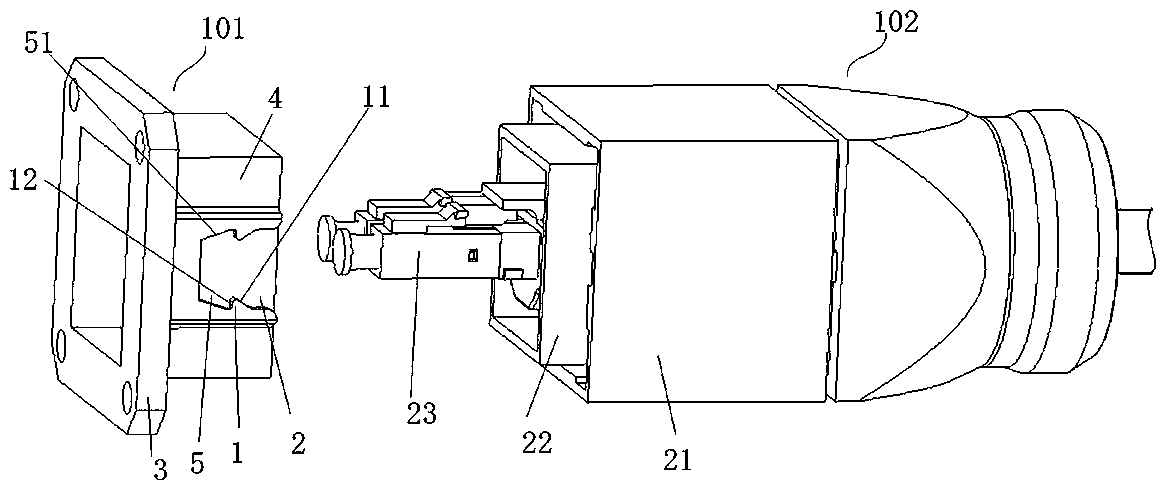
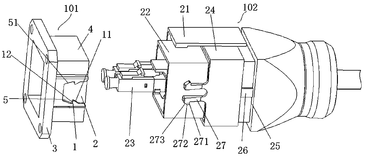
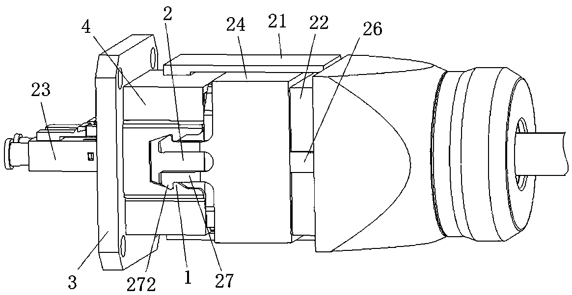
[0060] Such as Figure 1 to Figure 3 As shown, the connector includes a receptacle 101 and a plug 102 that are suitable for plugging. In this embodiment, the receptacle 101 and the plug 102 are both rectangular connectors, and the plug ends of the receptacle 101 and the plug 102 are defined as front ends. The socket 101 includes a socket housing 4, the socket housing 4 is fixed with a socket inner core (not shown), the plug 102 includes an inner housing 22, and the inner housing 22 is fixed with a plug inner core 23, between the socket 101 and When the plug 102 is inserted, the socket shell 4 and the inner shell 22 are docked, and the plug inner core 23 is also docked with the socket inner core. In other embodiments, the socket and plug may be polygonal connectors, or waist circular connectors.

[0061] Specifically, a locking sleeve 24 is set on the inner housing 22, and the locking sleeve 24 constitutes a locking member. The rear end of the inner housing 22 is provided with...

specific Embodiment 6

[0086] The difference between the specific embodiment 6 of the connector of the present invention and the specific embodiment 1 of the connector is that the hooking part is arranged along the radial direction of the plug housing, and is located on the inner side of the claw. During the rearward movement, the hooking part moves along the circumferential direction of the plug housing to realize unlocking with the hooking matching part, thereby realizing the separation of the plug and the socket.

[0087] The specific embodiment of the plug of the present invention, the structure of the plug in this embodiment is the same as that of the plug in any one of the specific embodiments 1-6 of the above-mentioned connector, and will not be repeated here.


PUM


Abstract

The invention relates to a connector and a plug thereof. The plug comprises a plug shell, wherein the front end of plug shell is a plugging end. The plug comprises an elastic claw, wherein the elasticclaw is arranged on the plug shell, the elastic claw is provided with a hooking part, the hooking part is used for being matched with a hooking matching part on a socket shell in a hooking manner soas to lock and fix the plug and the socket which are assembled in a plugging manner, and the elastic claw is provided with a passive unlocking part. The plug further comprises an unlocking piece, wherein the unlocking piece is movably assembled on the plug shell in the front-back direction, the unlocking piece is provided with an active unlocking part, and when the unlocking piece moves in the front-back direction, the active unlocking part and the passive unlocking part are matched in a pushing mode to drive the hooking part to act in the circumferential direction of a connector shell, so that the hooking part is separated from the corresponding hooking matching part, and then unlocking of the plug and the socket is achieved; and at least one of the active unlocking part and the passive unlocking part is of an inclined plane structure. No auxiliary device is needed in the unlocking process, and the unlocking mode is simple.

Description

technical field [0001] The invention relates to a connector and its plug. Background technique [0002] After the existing connectors are connected to each other, they are generally locked by locking methods such as threads or bayonet sockets. However, these locking methods require rotating the connectors, and the operation is relatively cumbersome. In response to the above problems, connector assemblies that can be locked and unlocked by claws have appeared on the market. [0003] The Chinese invention patent application with the application publication number CN108463926A discloses a plug-in connector. The plug-in connector has a housing. The housing has a plug-in terminal and an outlet terminal. The element can move between the first locking position and the second unlocking position. The locking element is provided with an opening and an introduction slope, and the locking element can be manually moved from the first locking position to the second by inserting an auxili...

Claims


Application Information

Patent Timeline
Patent Type & Authority Applications(China)
IPC IPC(8): H01R13/639H01R13/633H01R13/502H01R24/00
CPCH01R13/502H01R13/633H01R13/639H01R24/00
Inventor 韩云钊刘乃常李卫可徐耕崔艳磊武学顺杨帅杰徐骏
Owner CHINA AVIATION OPTICAL-ELECTRICAL TECH CO LTD
Why Eureka
Try Eureka