
A speed bump control system and a speed bump control method

A control system and control method technology, applied in the field of transportation, can solve problems such as speed bumps, speed bumps, driving comfort, etc.

Active Publication Date: 2020-10-30
江苏东交工程设计顾问有限公司
View PDF8 Cites 0 Cited by
  • Summary
  • Abstract
  • Description
  • Claims
  • Application Information

AI Technical Summary

Problems solved by technology

[0004] This application provides a speed reduction belt control system and a speed reduction belt control method, which can solve the problem that the existing speed reduction belt has an impact on the driving comfort of all passing vehicles. There is also the problem of turbulence

Method used


Image

  • A speed bump control system and a speed bump control method
  • A speed bump control system and a speed bump control method
  • A speed bump control system and a speed bump control method

Examples


Embodiment Construction

[0035] In order to make the purposes, technical solutions and advantages of the embodiments of the present application clearer, the technical solutions in the embodiments of the present application will be clearly and completely described below in conjunction with the drawings in the embodiments of the present application. Obviously, the described embodiments It is a part of the embodiments of this application, not all of them. The components of the embodiments of the application generally described and illustrated in the figures herein may be arranged and designed in a variety of different configurations.

[0036] Accordingly, the following detailed description of the embodiments of the application provided in the accompanying drawings is not intended to limit the scope of the claimed application, but merely represents selected embodiments of the application. Based on the embodiments in this application, all other embodiments obtained by persons of ordinary skill in the art w...


PUM


Abstract

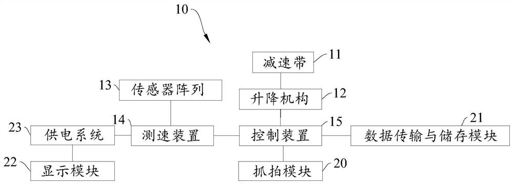
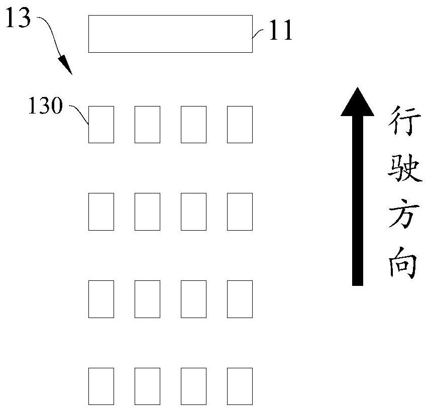
The invention discloses a deceleration strip control system and a deceleration strip control method. The deceleration strip control system comprises a deceleration strip, a lifting mechanism, a sensorarray, a speed measuring device and a control device. The sensor array comprises a plurality of rows of stress sensors, each row of stress sensors comprises a plurality of stress sensors arranged atintervals in the direction parallel to the deceleration strip, and every two adjacent rows of stress sensors are arranged at intervals in the direction perpendicular to the deceleration strip; the speed measuring device is connected with the sensor array and used for detecting the speed of the vehicle passing between every two adjacent rows of stress sensors; the control device is connected with the speed measuring device and used for controlling the lifting mechanism to act according to the speed, obtained by the speed measuring device, of the vehicle passing between every two adjacent rows of stress sensors. According to the technical scheme provided by the invention, the problems that an existing deceleration strip influences the driving comfort of all passing vehicles, and even if an automobile is not overspeed, the automobile jolts when driving to the position of the deceleration strip can be solved.

Description

technical field [0001] The present application relates to the field of traffic technology, in particular, to a speed bump control system and a speed bump control method. Background technique [0002] In a specific road section, in order to limit the speed of vehicles and ensure traffic safety, it is usually necessary to set speed bumps on the road to remind vehicles to slow down in advance. [0003] However, the existing speed bumps have an impact on the driving comfort of all passing vehicles, even if they are not overspeeding, bumps will also occur when driving to the speed bumps. Contents of the invention [0004] This application provides a speed reduction belt control system and a speed reduction belt control method, which can solve the problem that the existing speed reduction belt has an impact on the driving comfort of all passing vehicles. There are also bumping issues. [0005] In a first aspect, a speed bump control system is provided, including a speed bump, ...

Claims


Application Information

Patent Timeline
Patent Type & Authority Patents(China)
IPC IPC(8): E01F9/529E01F11/00G08G1/054
CPCE01F11/00E01F9/529G08G1/054
Inventor 李华张苏龙马凌毛益佳王彤陈广辉潘芳方芳王青张仁豪王捷叶炜凌高祥
Owner 江苏东交工程设计顾问有限公司
Learn More