
On-orbit correction method for optical axis pointing accuracy of remote sensor

An optical axis pointing and remote sensor technology, applied in the field of remote sensors, can solve problems such as positioning accuracy errors, achieve the effects of avoiding transmission errors, improving optical axis pointing accuracy, and meeting accuracy requirements

Active Publication Date: 2020-06-02
CHANGCHUN INST OF OPTICS FINE MECHANICS & PHYSICS CHINESE ACAD OF SCI
View PDF12 Cites 2 Cited by
  • Summary
  • Abstract
  • Description
  • Claims
  • Application Information

AI Technical Summary

Problems solved by technology

[0005] Aiming at the problem in the prior art that there is an error in the on-orbit limb positioning accuracy of the scanning mirror for trace gas observation, the embodiment of the present invention provides a method for on-orbit correction of the optical axis pointing accuracy of the remote sensor, thereby effectively improving the optical accuracy of the remote sensor. Axis pointing accuracy

Method used


Image

  • On-orbit correction method for optical axis pointing accuracy of remote sensor
  • On-orbit correction method for optical axis pointing accuracy of remote sensor
  • On-orbit correction method for optical axis pointing accuracy of remote sensor

Examples


Embodiment Construction

[0023] In order to enable those skilled in the art to better understand the solutions of the present invention, the following will clearly and completely describe the technical solutions in the embodiments of the present invention in conjunction with the drawings in the embodiments of the present invention. Obviously, the described embodiments are only It is an embodiment of a part of the present invention, but not all embodiments. Based on the embodiments of the present invention, all other embodiments obtained by persons of ordinary skill in the art without making creative efforts shall fall within the protection scope of the present invention.

[0024] The terms "first", "second", "third", "fourth", etc. (if any) in the description and claims of the present invention and the above drawings are used to distinguish similar objects and not necessarily Describe a specific order or sequence. It is to be understood that the terms so used are interchangeable under appropriate cir...


PUM


Abstract

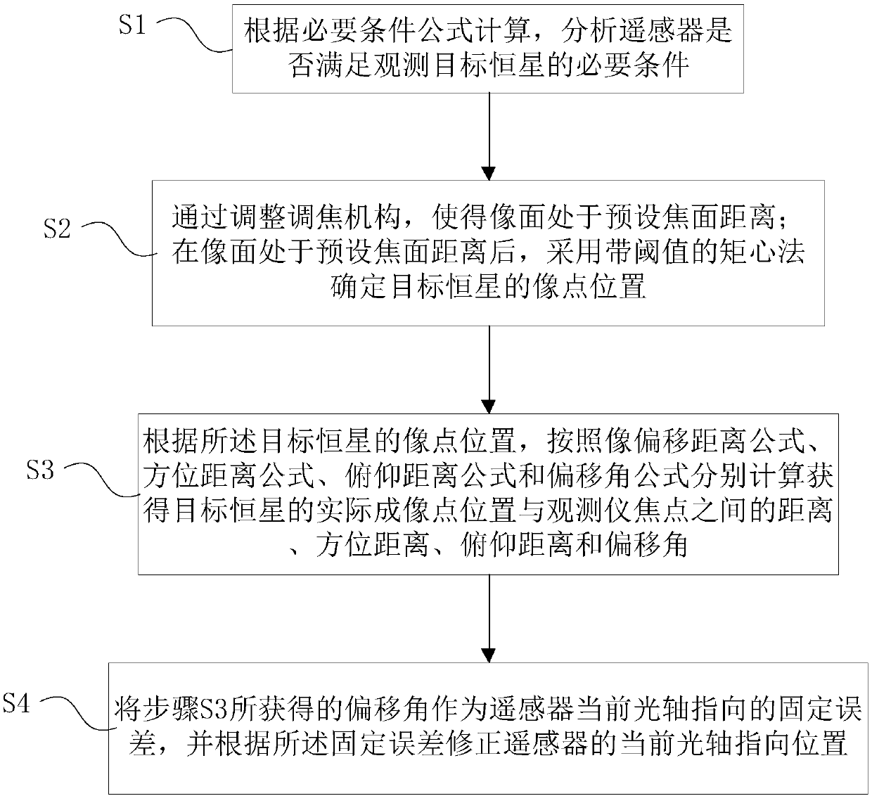
The embodiment of the invention discloses an on-orbit correction method for the optical axis pointing accuracy of a remote sensor. The method comprises the following steps: calculating and analyzing whether a remote sensor meets a necessary condition for observing a target fixed star according to a necessary condition formula; arranging an image plane at a preset focal plane distance by adjustinga focusing mechanism; after the image plane is located at the preset focal plane distance, determining the image point position of the target fixed star by adopting a moment center method with a threshold value; according to the image point position of the target fixed star, calculating a distance, an azimuth distance, a pitch distance and an offset angle between the actual imaging point positionof the target fixed star and the focus of the observer respectively based on an image offset distance formula, an azimuth distance formula, a pitch distance formula and an offset angle formula; withthe obtained deviation angle as a fixed error of the current optical axis pointing of the remote sensor, correcting the current optical axis pointing position of the remote sensor according to the fixed error. The method can correct the optical axis pointing in orbit, thereby effectively improving the optical axis pointing precision of the remote sensor.

Description

technical field [0001] The invention relates to the technical field of remote sensors, in particular to an on-orbit correction method for optical axis pointing accuracy of remote sensors. Background technique [0002] Some trace gas elements in the atmosphere have vertical distribution characteristics and present a large gradient. For example, an altitude error of 500 meters in the tangential direction of the Earth's limb will increase the retrieval error of stratospheric ozone by 10%, and the retrieval error of tropospheric ozone by 20%. When the observation distance is relatively long (such as greater than 3000 kilometers), the error of the positioning angle of the scanning mirror 1' will cause the error of 1 km in the limb tangential height, so the limb observation of trace gases needs to precisely control the optical axis at the earth's edge. The height of the edge tangent to ensure the inversion accuracy of the vertical distribution of atmospheric components. [0003]...

Claims


Application Information

Patent Timeline
IPC IPC(8): G01C25/00
CPCG01C25/00
Inventor 吴伟平王淑荣
Owner CHANGCHUN INST OF OPTICS FINE MECHANICS & PHYSICS CHINESE ACAD OF SCI
Learn More