Combined box girder and manufacturing method thereof

A manufacturing method and combined box technology, which is applied in bridges, bridge parts, bridge construction, etc., can solve the problems of heavy workload of box girders, and achieve the effects of small on-site workload, reduced environmental impact, and reduced difficulty in quality control

Pending Publication Date: 2020-06-05
ZHEJIANG PROVINCIAL INST OF COMM PLANNING DESIGN & RES CO LTD
View PDF0 Cites 0 Cited by
  • Summary
  • Abstract
  • Description
  • Claims
  • Application Information

AI Technical Summary

Problems solved by technology

[0005] The purpose of the present invention is to provide a combined box girder and its manufacturing method to solve the technical problem of large field operations of box girders in the prior art

Method used


Image

  • Combined box girder and manufacturing method thereof
  • Combined box girder and manufacturing method thereof
  • Combined box girder and manufacturing method thereof

Examples


no. 1 example

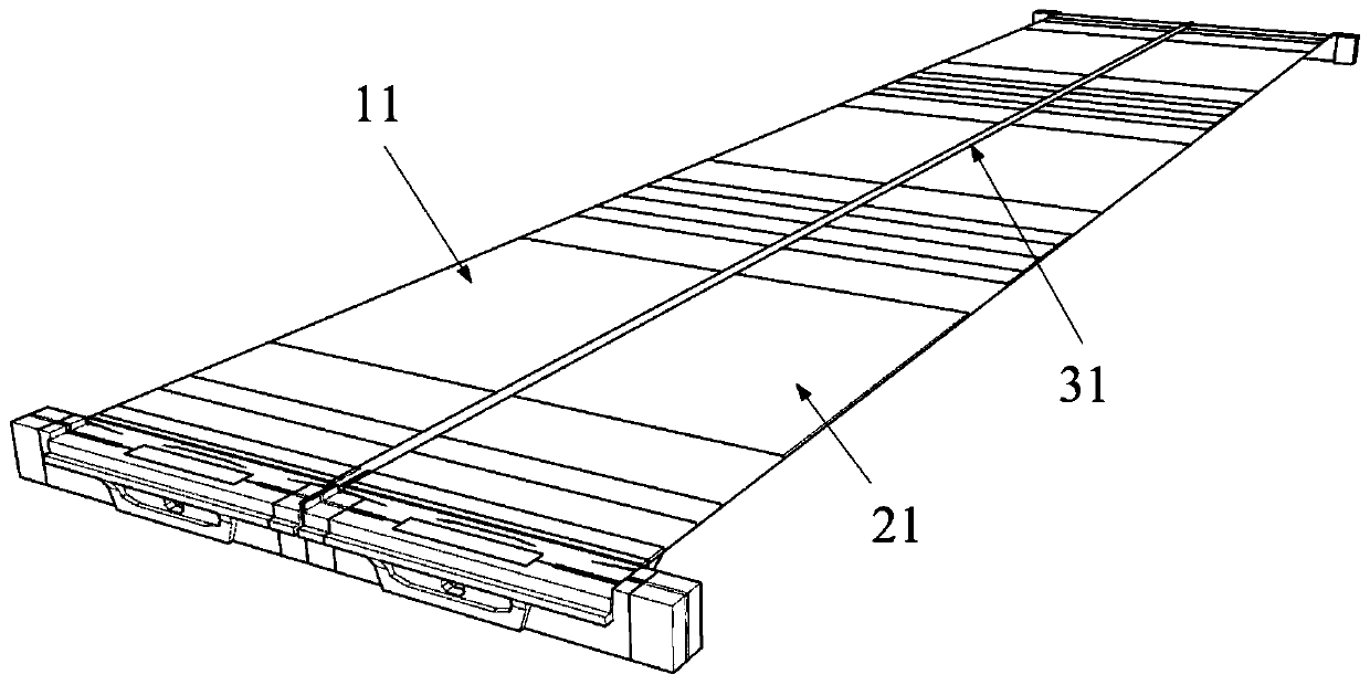
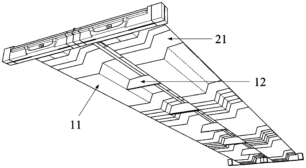
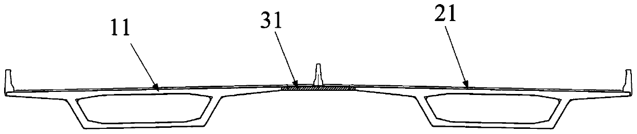
[0052] Such as Figure 1-Figure 13 As shown, the combined box girder provided by the embodiment of the present invention includes: a first beam section 11 and a second beam section 21, and there is a first gap between the first beam section 11 and the second beam section 21, and the first gap is set There are a first connecting piece 13 and a second connecting piece 23, the first connecting piece 13 is connected to the flange plate 34 of the first beam section 11, the second connecting piece 23 is connected to the flange plate 34 of the second beam section 21, and the second connecting piece 13 is connected to the flange plate 34 of the second beam section 21. The first connecting piece 13 and the second connecting piece 23 are fixed by the first binding piece 33 , and the first gap is poured with concrete so that the first joint 31 is formed between the first beam section 11 and the second beam section 21 .

[0053] Specifically, the first beam section 11 and the second beam ...

no. 2 example

[0072] This embodiment provides a method for manufacturing a composite box girder, which is used to manufacture the composite box girder provided in the first embodiment above, including:

[0073] manufacturing the first beam section and the second beam section with the first connector secured to the flange plate of the first beam segment and the second connector secured to the flange plate of the second beam segment;

[0074] Assembling the first beam section and the second beam section, adjusting the width of the first gap between the first beam section and the second beam section;

[0075] connecting the bottom formwork with the first beam section and the second beam section respectively, and the bottom side formwork is located below the first gap;

[0076] binding the first connecting piece and the second connecting piece together through the first binding piece;

[0077] Concrete is poured at the first gap to connect the first beam section to the second beam section.

...


PUM


Abstract

The invention provides a combined box girder and a manufacturing method thereof, and relates to the technical field of bridge design and construction. The combined box girder comprises a first beam section and a second beam section, a first gap is formed between the first beam section and the second beam section; a first connecting piece and a second connecting piece are arranged in the first gap;the first connecting piece is connected with a flange plate of the first beam section, the second connecting piece is connected with a flange plate of the second beam section, the first connecting piece and the second connecting piece are fixed through a first binding piece, and concrete is poured into the first gap so that a first joint can be formed between the first beam section and the secondbeam section. The first beam section and the second beam section in the combined box beam do not need to be manufactured on site and can be transported to the site after being manufactured, so that the field operation amount is relatively small, the influence on the environment is reduced, and the quality control difficulty is reduced.

Description

technical field [0001] The invention relates to the technical field of bridge design and construction, in particular to a composite box girder and a manufacturing method thereof. Background technique [0002] At present, for urban viaducts and interchange hub projects, super-wide box girders and special-shaped bridge structures are inevitable. [0003] According to the road alignment requirements and the changing characteristics of the road's longitudinal and transverse slopes, in the overall layout design of the bridge, the complex special-shaped section at the junction of the ramp needs to adopt a special-shaped widening curved bridge, which is often in the shape of "herringbone" and "pants". structure. [0004] In the past, design schemes such as multi-chamber box girder special-shaped structures were generally adopted. The multi-chamber ultra-wide box girder is a non-standard special-shaped structure with complex structural forces. In addition to bearing bending moment...

Claims


Application Information

Patent Timeline
Patent Type & Authority Applications(China)
IPC IPC(8): E01D2/04E01D19/06E01D21/00
CPCE01D2/04E01D19/067E01D21/00
Inventor 李磊卢也森王昌将
Owner ZHEJIANG PROVINCIAL INST OF COMM PLANNING DESIGN & RES CO LTD
Why Eureka
Try Eureka