

Magnetoresistance effect element and manufacturing method and apparatus thereof, and magnetic reproducing apparatus
A magnetoresistance and element technology, applied in the field of magnetoresistance effect element manufacturing equipment, can solve problems such as narrowing the track width of difficult magnetic heads, and achieve the effects of narrow track width, increased compatibility, and compatible recording density
- Summary
- Abstract
- Description
- Claims
- Application Information
AI Technical Summary
Problems solved by technology
Method used
Image

Examples
no. 1 approach
[0036] figure 1 is a cross-sectional view schematically showing the first embodiment of the magnetoresistance effect element according to the present invention.
[0037] exist figure 1 In , the air bearing surface (ABS) facing the disk media (not shown) is shown. figure 1 Among them, on a substrate (not shown), a seed layer 2, an antiferromagnetic layer 12, a pinning layer 3, an intermediate layer 6, a free layer 5, a recombination layer 8 and a cap layer 10 are sequentially stacked on another one above. The seed layer 2 and the cap layer 10 are mainly composed of conductive thin films, such as Ta. The antiferromagnetic layer 12 is mainly composed of a metallic magnetic material, mainly PtMn. The pinned layer 3 is mainly composed of stacked magnetic films such as CoFe / Ru / CoFe. The intermediate layer 6 is mainly composed of conductive thin films such as Cu, Au, Ag, Pt, Pd, Ir or Os. The free layer 5 is mainly composed of a metal magnetic material mainly CoFe / NiFe.
[003...
no. 2 approach
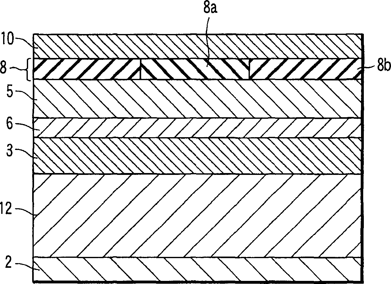
[0049] Figure 5 is a cross-sectional view schematically showing a second embodiment of the magnetoresistance effect element according to the present invention. exist Figure 5 in, with figure 1 The same parts in are denoted by the same reference numerals. Only parts different from the latter will be described.
[0050] exist Figure 5 Among them, the intermediate layer 6 formed between the pinned layer 3 and the free layer 5 includes a current control region 8a and an insulating material region 8b. That is, in the second embodiment, the current control region 8a and the insulating material region 8b are in figure 1 Formed in the intermediate layer 6, so that the intermediate layer 6 also plays the role of composite layer 8.
[0051] Figure 6 is a conceptual representation that includes Figure 5 A cross-sectional view of the structure of the main part of the magnetic head of the magnetoresistance effect element. as in figure 2 in Figure 6 In this case, bias film...
no. 3 approach
[0055] Next, a method of manufacturing a magnetoresistance effect element according to a third embodiment of the present invention will be explained. The magnetoresistance effect element related to the present invention is manufactured using an apparatus combining a vacuum vapor deposition unit for forming a metal thin film and an ion irradiation unit for irradiating ion beams on the metal thin film. The vacuum vapor deposition unit has the function of processing samples in an oxygen atmosphere. That is to say, a film-forming unit is used in combination, a unit having the function of oxidizing a sample under proper temperature control using an appropriate oxygen partial pressure and an appropriate exposure time, and an ion radiation unit are used to realize the manufacturing equipment of the magnetoresistance effect element of the present invention .
[0056] Figure 9 is to help explain Figure 5 A cross-sectional view of the first step in the manufacturing method of the m...
PUM
 Abstract
Description
Claims
Application Information