IF derived data slicer reference voltage circuit

a data slicer and reference voltage technology, applied in the field of receiver circuits, can solve the problems of shortening the time of data signal and erroneously constant output, and achieve the effect of low cost and without sacrificing sensitivity

Inactive Publication Date: 2005-09-01
OMRON AUTOMOTIVE ELECTRONICS CO LTD
View PDF14 Cites 6 Cited by
  • Summary
  • Abstract
  • Description
  • Claims
  • Application Information

AI Technical Summary

Benefits of technology

[0010] The use of this data, which contains a component with a higher frequency, provides a much larger number of “edges” in the signal (inasmuch as the overall frequency is higher than that of the filtered data). Accordingly, the duration of the data signal is shorter and the problem wherein the capacitor is induced to charge to peak voltage and thus generates an output which remains erroneously constant for long periods of time, is obvia

Problems solved by technology

Accordingly, the duration of the data signal is shorter and the problem wherein the capacitor is induced to charge t

Method used


Image

  • IF derived data slicer reference voltage circuit
  • IF derived data slicer reference voltage circuit
  • IF derived data slicer reference voltage circuit

Examples


Embodiment Construction

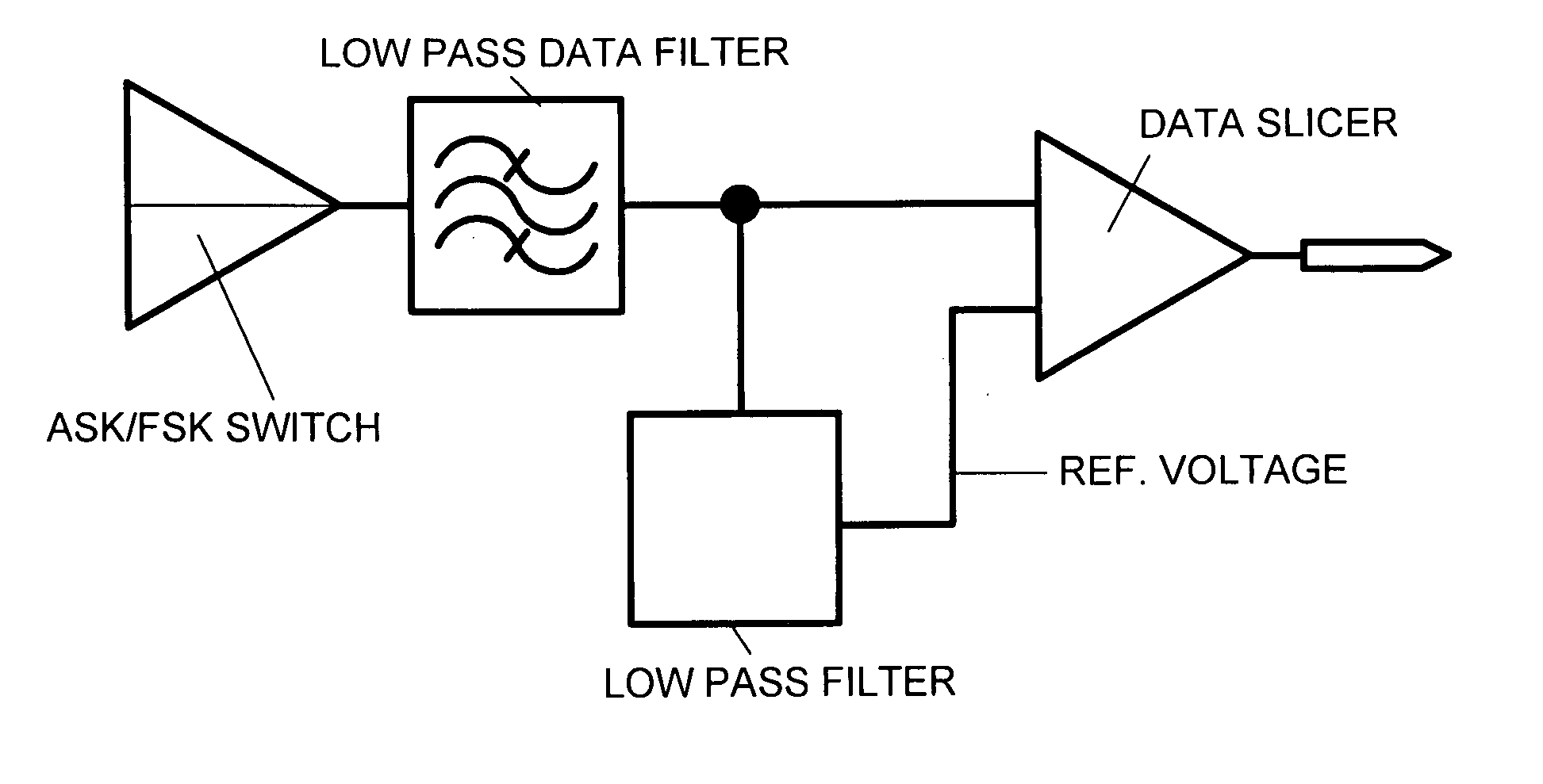
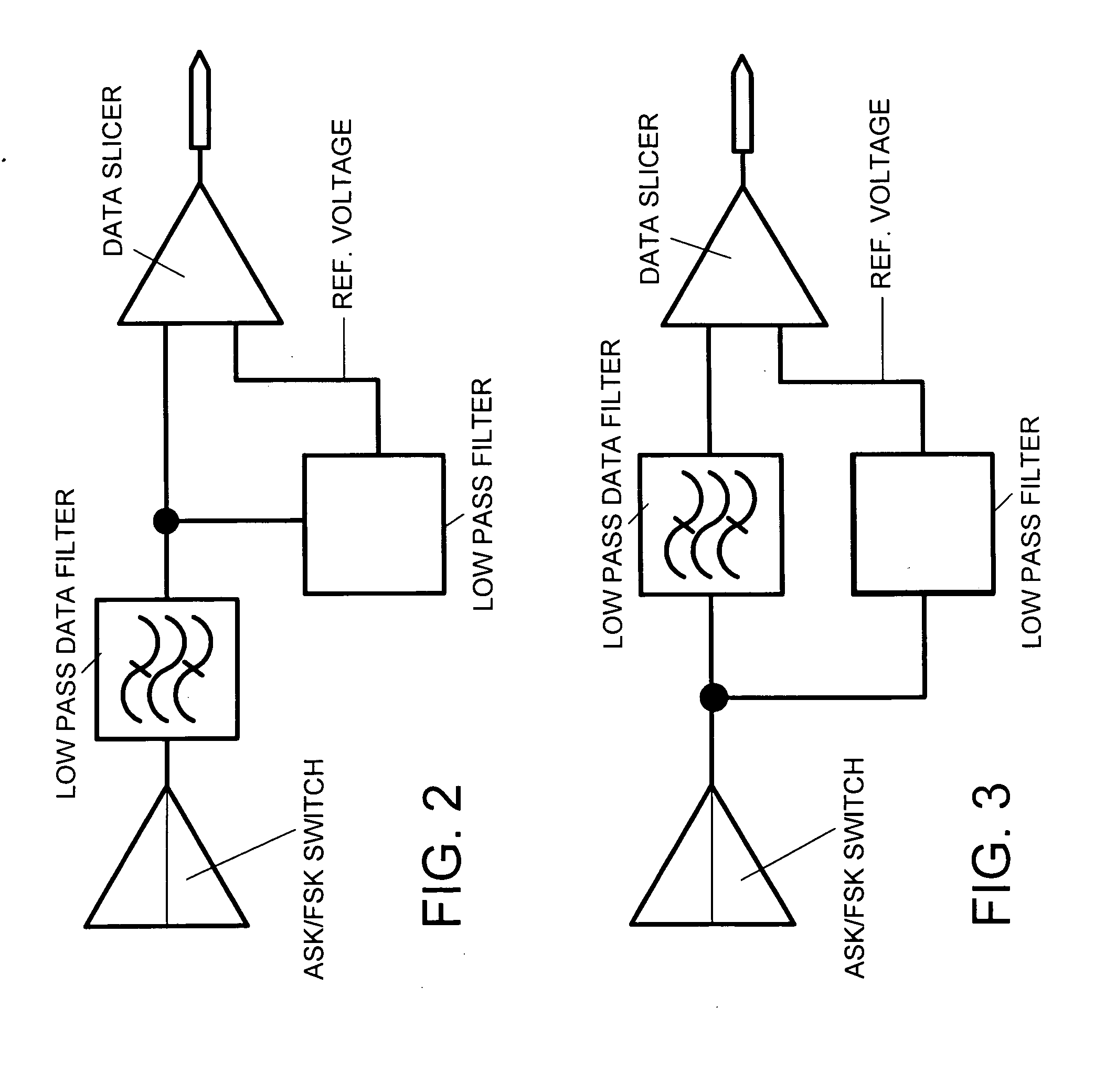
[0029] As noted above, FIGS. 2 and 3 compare the prior art with the arrangement which exemplifies the present invention. The use of the higher frequency data signal which is tapped off upstream of the low pass filter which is interposed between the ASK / FSK switch and the comparator that functions as the single bit A / D converter.

[0030]FIG. 4 depicts the arrangement wherein the low pass filter which is shown in FIG. 3 and which is used to develop the reference voltage which is used in the comparator to provide the data slice function, comprises a simple RC circuit.

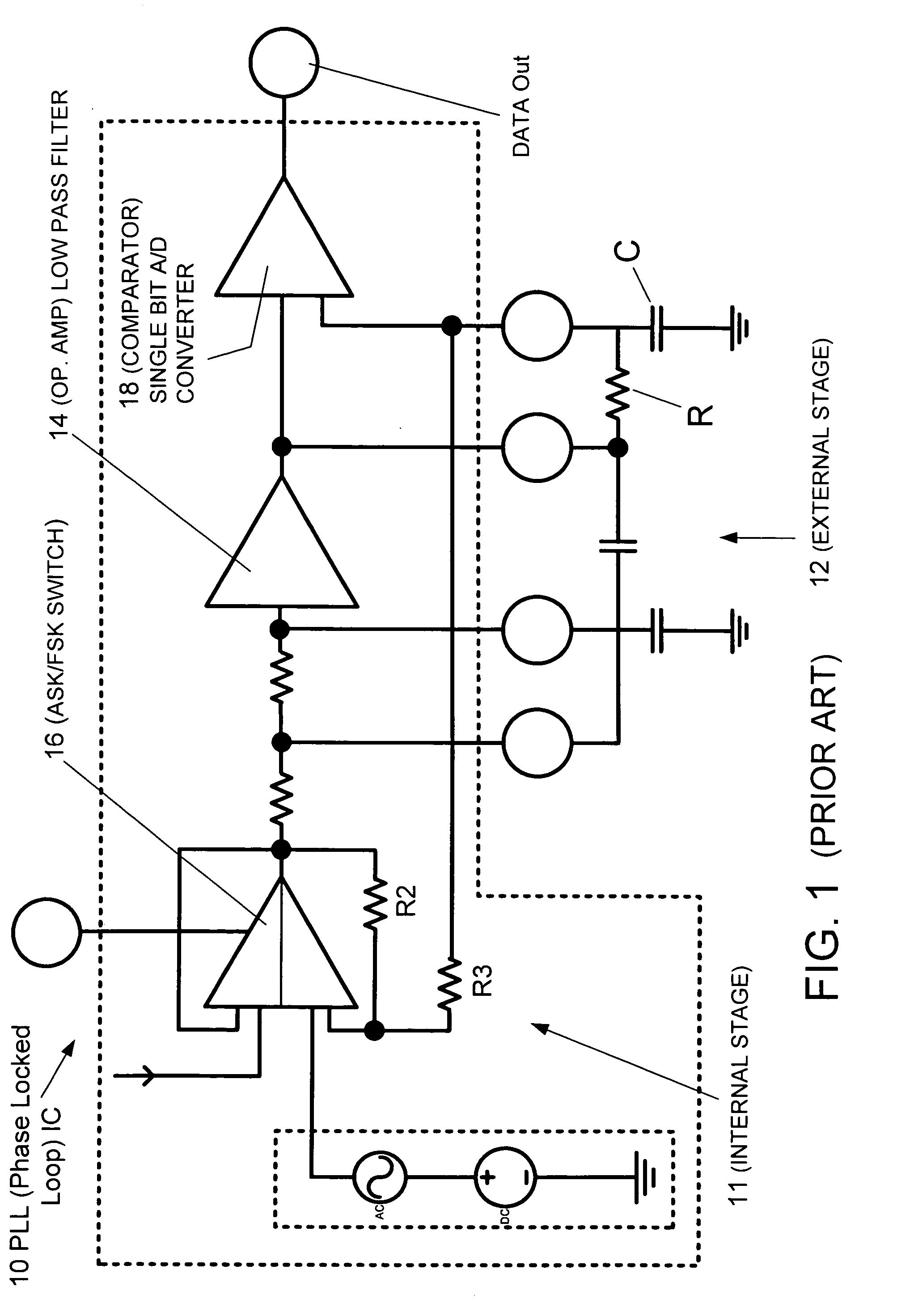
[0031]FIG. 5 shows a circuit arrangement which has been adapted via a simplification of the prior art shown in FIG. 1, to change from the configuration depicted in FIG. 2 to that which is depicted in FIG. 3. This transformation is achieved by removing the resistor designated R from the external stage and making use of the resistors R2 and R3 which are associated with the ASK / FSK switch. This established an RC circuit where...


PUM


Abstract

A method of deriving a reference voltage for a data slicer features supplying a signal to a filter and filtering the signal; supplying the filtered signal to a comparator which comprises the data slicer; passing the signal prior filtering through an RC circuit; and using the output of the RC circuit as the reference voltage for the comparator.

Description

BACKGROUND OF THE INVENTION [0001] 1. Field of the Invention [0002] The present invention relates generally to a receiver circuit for use in devices such as keyless entry arrangement for automotive vehicles and the like, and more specially to a receiver which includes a circuit arrangement that provides a threshold voltage for a data slicer which forms part of the receiver, in a manner which allows the receiver to be produced economically and without sacrificing sensitivity. [0003] 2. Description of the Relevant Art [0004]FIG. 1 schematically depicts a prior art circuit arrangement 10 and shows the internal 11 and external stages 12 of a PLL (phase-locked loop) IC. In this figure, the internal stages 11 are shown within the broken line and are sealed within the chip. The circles denote the pins which permit electrical connection between the internal and external stages 11, 12. In this arrangement, the external stage 12 comprises capacitors and resistors which are connected in the il...

Claims


Application Information

Patent Timeline
IPC IPC(8): H04L5/12H04L25/06H04L27/00H04L27/06H04L27/148
CPCH04L25/061H04L27/148H04L27/06H04L27/0008
Inventor BRANDWEIN, RICHARD PAUL JR.
Owner OMRON AUTOMOTIVE ELECTRONICS CO LTD
Why Eureka
Try Eureka