Touch control display panel

A touch display panel and substrate technology, applied in static indicators, instruments, electrical digital data processing, etc., can solve problems affecting the uniformity of touch sensing, poor touch function, affecting the minimum external force of sensing touch, etc. , to achieve the effects of increasing the sensing sensitivity and overall uniformity, reducing poor touch function or short circuit, and making the design more flexible and diverse

Active Publication Date: 2010-04-14
AU OPTRONICS CORP
View PDF2 Cites 1 Cited by
  • Summary
  • Abstract
  • Description
  • Claims
  • Application Information

AI Technical Summary

Problems solved by technology

[0005] However, the prior art has the following disadvantages: First, after multiple presses, the deformation of the main spacer 128a and the sensing bump 128b increases and the elastic restoring force becomes worse, causing the sensing gap Gs to shrink or even disappear, that is, , the first electrode 116 is in direct contact with the second electrode 126 at certain points, and this state will cause poor touch function or short circuit (touch function short), and in severe cases may also cause a touch on the top of the sensing bump 128b. The second electrode 126 is damaged
In other words, the aperture ratio of the panel itself will decrease, indirectly resulting in a decrease in light transmittance or an increase in the cost of the backlight module
[0008] Moreover, since the second electrode 126 on the sensing bump 128b has to be in contact with the first electrode 116 on the sensing pad structure 114b, the potential of the first electrode 116 changes to convert the touched position. Therefore, the first electrode The thickness of the alignment film material above 116 will also affect the minimum external force (activeforce) that can sense touch
The sensing pad height structure 114b known in the past is all formed by the differences in the stacking layers of the thin film transistor technology on the first substrate 110, so its height cannot be effectively improved.
Therefore, when the alignment film is transferred to the first substrate 110 by using APR (relief printing) method, the thickness of the remaining alignment film above the sensing pad structure 114b cannot be reduced due to the difference in height, which will affect the uniformity and The minimum external force required to sense the touch (active force)

Method used


Image

  • Touch control display panel
  • Touch control display panel
  • Touch control display panel

Examples


Embodiment Construction

[0083] In order to make the above and other objects, features and advantages of the present invention more comprehensible, preferred embodiments will be described in detail below together with the accompanying drawings.

[0084] It should be noted that the detailed structures presented as examples in the following different embodiments can be combined, replaced or omitted under reasonable circumstances, so as to meet different actual needs. Those skilled in the art should be able to understand the spirit and technical characteristics of the present invention after referring to the description of the following embodiments, and make reasonable changes and applications without departing from the scope of the spirit of the present invention. In addition, in order to facilitate the description and make the description easier to understand, the same reference numerals are used below to denote similar elements, and repeated text descriptions may be omitted.

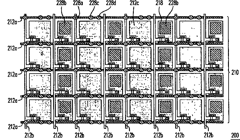
[0085] Figure 2A and ...


PUM


Abstract

The invention provides a touch-control display panel, comprising a first base plate, a second base plate and a liquid crystal layer. The first base plate comprises a plurality of sensing areas and a non-sensing area positioned outside the sensing areas, and each sensing area is internally provided with a first electrode. The second base plate comprises a plurality of main gap objects, a pluralityof sensing bumps, a plurality of first auxiliary gap objects and a plurality of second auxiliary gap objects; the main gap objects are connected to the non-sensing area of the first base plate; the sensing bumps are provided with a second electrode and corresponding to the sensing area, and maintain a sensing gap with the first base plate; the first auxiliary gap objects are corresponding to the non-sensing area and maintain a first auxiliary gap with the first base plate; the second auxiliary gap objects are corresponding to the non-sensing area and maintain a second auxiliary gap with the first base plate; the sensing gap is more than the first auxiliary gap and less than the second auxiliary gap.

Description

technical field [0001] The present invention relates to a touch display panel, and in particular to a built-in touch display panel. Background technique [0002] In recent years, with the rapid development of various applications such as information technology, wireless communication and information home appliances, in order to achieve more convenience, smaller volume and more humanization, the input devices of many information products have been replaced by traditional keyboards or slides. mouse etc. into a touch display panel (touch display panel). [0003] figure 1 A partial cross-sectional schematic diagram of a known touch display panel is shown. Please refer to figure 1 , the traditional touch display panel 100 includes a first substrate 110 , a second substrate 120 and a liquid crystal layer 130 . The second substrate 120 has main spacers 128 a , sensing bumps 128 b , auxiliary spacers 128 c and second electrodes 126 . The first substrate 110 has a sensing pad st...

Claims


Application Information

Patent Timeline
Patent Type & Authority Patents(China)
IPC IPC(8): G06F3/041G02F1/133
Inventor 陈政德程琮钦周文彬李锡烈黄伟明
Owner AU OPTRONICS CORP
Why Eureka
Try Eureka