Handheld cleaning appliance

a cleaning appliance and hand-held technology, applied in the field of hand-held vacuum cleaners, can solve the problems of affecting the performance or capacity of the cyclonic separator, and the appliance is therefore relatively unstable, so as to increase the stability of the base surface of the appliance, and enhance the stability of the main body

Active Publication Date: 2009-12-17
DYSON TECH LTD
View PDF4 Cites 139 Cited by
  • Summary
  • Abstract
  • Description
  • Claims
  • Application Information

AI Technical Summary

Benefits of technology

[0006]It is therefore an object of the present invention to provide a handheld cleaning appliance incorporating a cyclonic separator which is oriented in a generally upright configuration for improved capacity and performance, the appliance being more convenient and stable to store on a flat surface.
[0008]By providing a base surface of the appliance, which is made up of a base surface of the main body and a base surface of the cyclonic separator, the appliance is provided with a substantial base surface on which the appliance can be stably and reliably supported. This is also achieved without substantially increasing the size of the appliance as a whole.
[0010]In a preferred embodiment, the main body includes a motor and / or battery unit arranged above the base surface of the main body. In this arrangement, the centre of gravity of the motor and / or battery unit passes through the base surface of the main body which enhances the stability of the main body when it is supported on the base surface thereof. More preferably, the motor and / or battery unit is arranged immediately above the base surface of the main body for further enhancing the stability of the main body.
[0011]It is also preferred that the width of the base surface of the main body is at least one half of the width of the cyclonic separator. This provides further increased stability of the base surface of the appliance.

Problems solved by technology

This can affect the performance of the cyclonic separator or its capacity to collect dirt and dust.
However, the base surface of the cyclonic separator is relatively small in comparison to the appliance as a whole and the appliance is therefore relatively unstable when balanced on the base surface of the cyclonic separator.

Method used


Image

  • Handheld cleaning appliance
  • Handheld cleaning appliance
  • Handheld cleaning appliance

Examples


Embodiment Construction

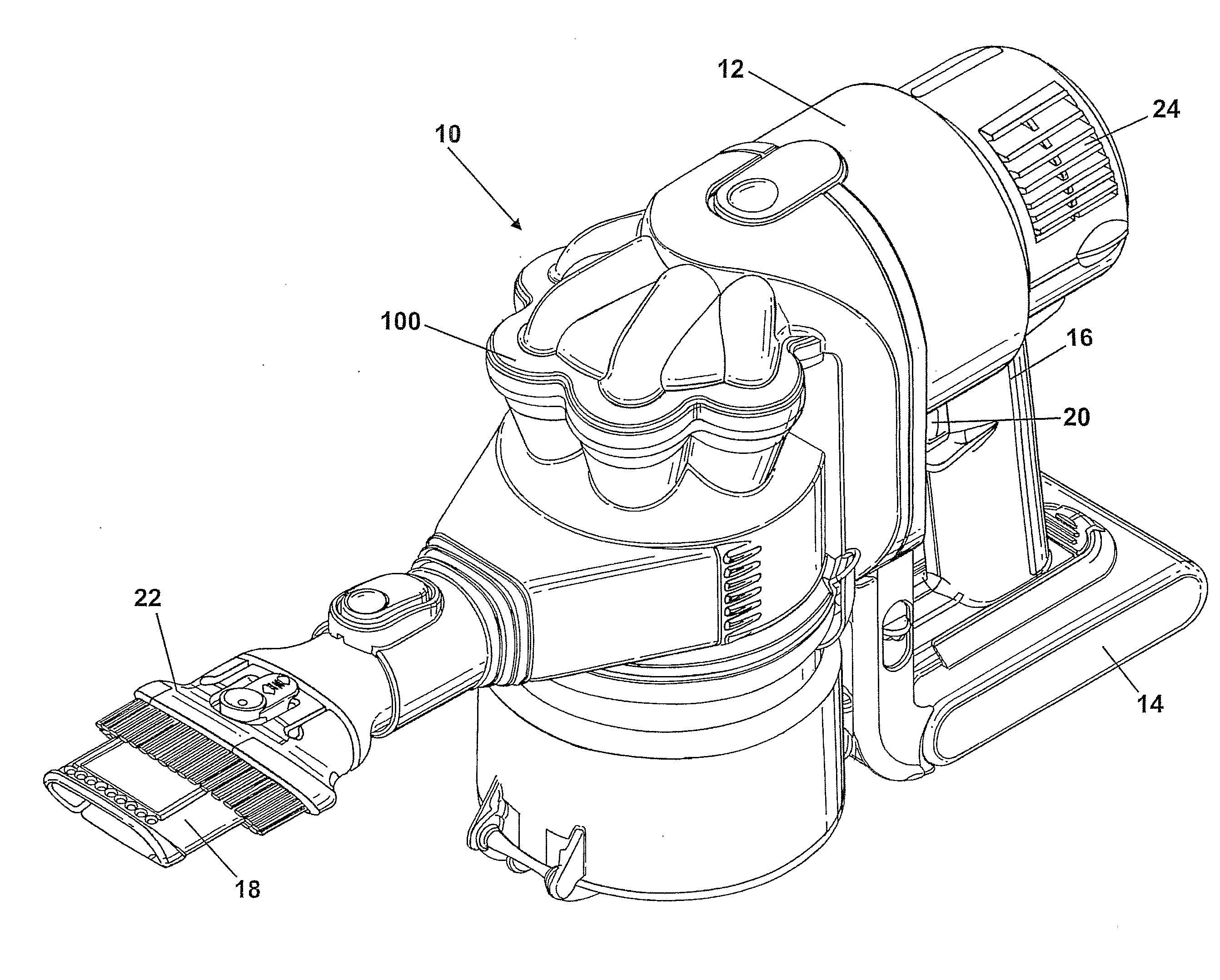
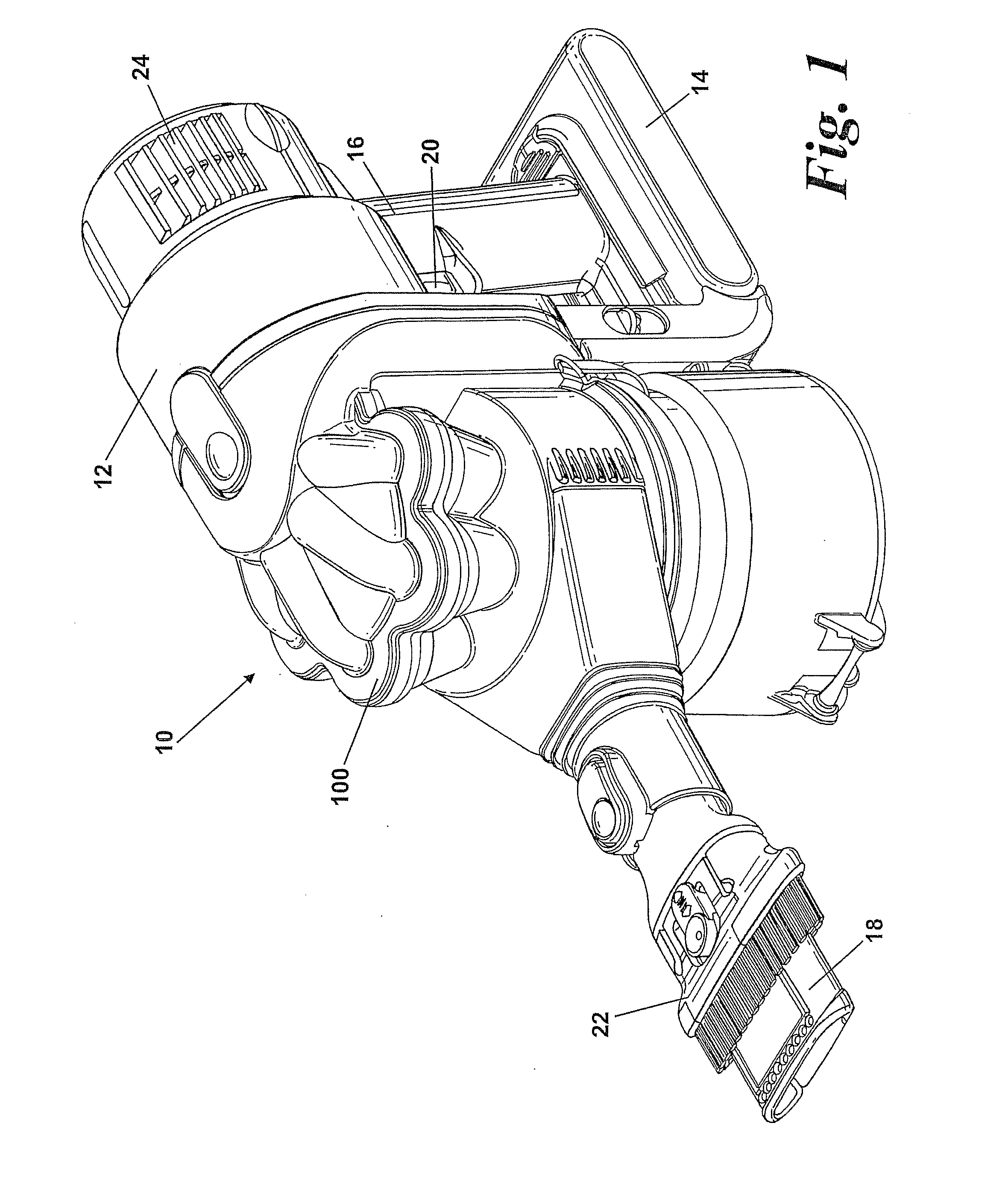
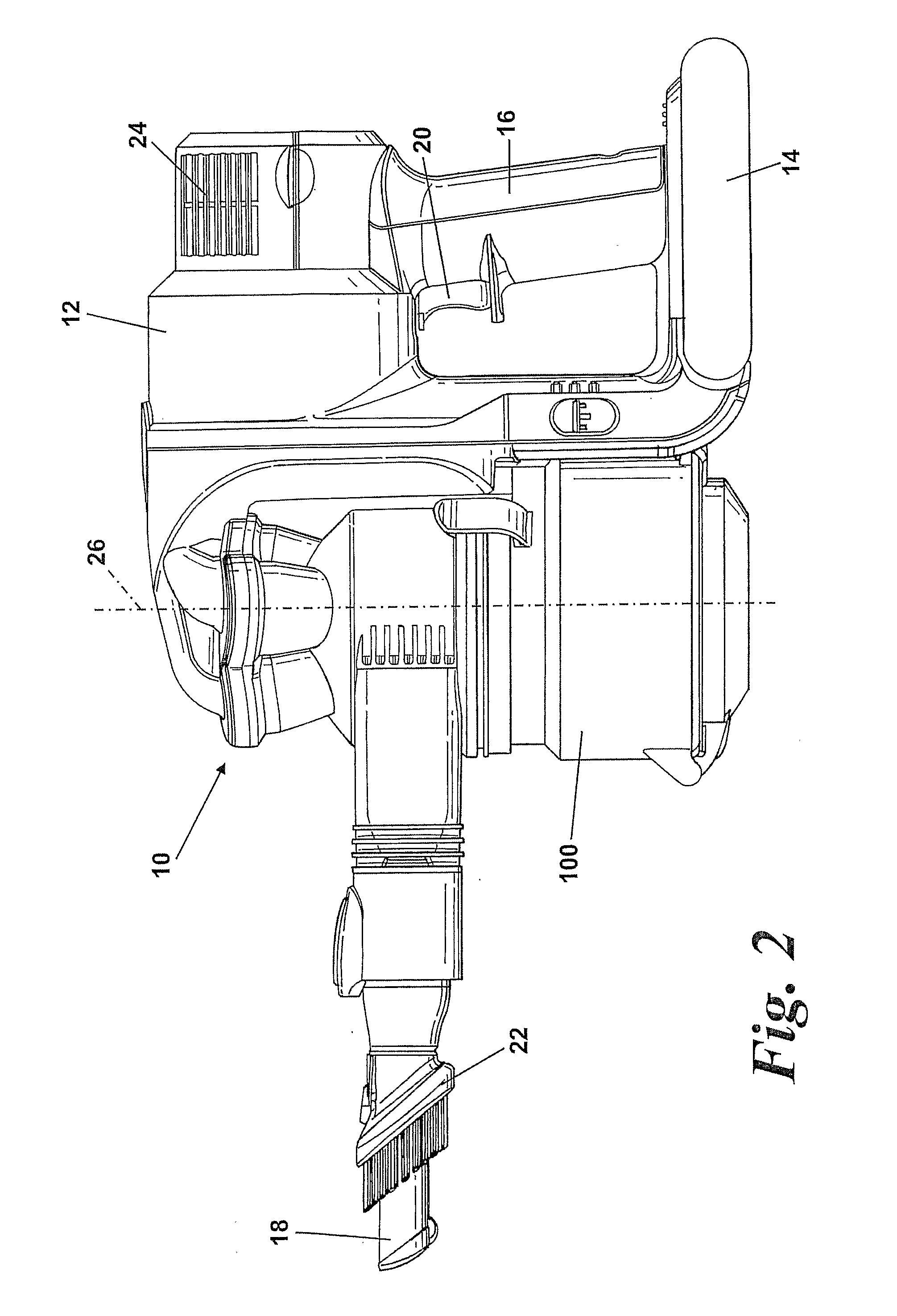
[0018]FIGS. 1 and 2 show a handheld vacuum cleaner 10. The handheld vacuum cleaner 10 has a main body 12 which houses a motor and fan unit (not shown). The main body 12 also includes a power source 14 such as a battery. A handle 16 is provided on the main body 12 for manipulating the handheld vacuum cleaner 10 in use. A cyclonic separator 100 is attached to the main body 12. A dirty air inlet 18 extends from a portion of the cyclonic separator 100 remote from the main body 12. A brush tool 22 is slidably mounted on the distal end of the dirty air inlet 18. A set of exhaust vents 24 are provided on the main body 12 for exhausting air from the handheld vacuum cleaner 10.

[0019]The cyclonic separator 100 is located between the main body 12 and the dirty air inlet 18. Consequently, the cyclonic separator 100 is located between the handle 16 and the dirty air inlet 18. The cyclonic separator 100 has a longitudinal axis 26 which extends in a generally upright direction so that the axis 26,...


PUM

PropertyMeasurementUnit
shapeaaaaaaaaaa
widthaaaaaaaaaa
sizeaaaaaaaaaa

Abstract

A handheld cleaning appliance includes a dirty air inlet, a clean air outlet and separating apparatus for separating dirt and dust from an airflow in an airflow path leading from the air inlet to the air outlet. The cyclonic separator is arranged in a generally upright orientation. A base surface of the main body and a base surface of the cyclonic separator together form a base surface of the appliance for supporting the appliance on a surface. By providing a base surface of the appliance which is made up of the base surface of the main body and the base surface of the cyclonic separator, the appliance is provided with a substantial base surface on which the appliance can be stably and reliably supported. This is also achieved without substantially increasing the size of the appliance as a whole.

Description

REFERENCE TO RELATED APPLICATIONS[0001]This application is a national stage application under 35 USC 371 of International Application No. PCT / GB2007 / 002540, filed Jul. 6, 2007, which claims the priority of United Kingdom Application Nos. 0614235.0 and 0618492.3, filed Jul. 18, 2006, and Sep. 20, 2006, respectively, the contents of which prior applications are incorporated herein by reference.FIELD OF THE INVENTION[0002]The invention relates to a handheld cleaning appliance particularly, but not exclusively, to a handheld vacuum cleaner. More particularly, the invention relates to a handheld cleaning appliance having a cyclonic separator.BACKGROUND OF THE INVENTION[0003]Handheld vacuum cleaners are well known and have been manufactured and sold by various manufacturers for several years. Typically, a handheld vacuum cleaner comprises a casing which houses a motor and fan unit for drawing air into the cleaner via an inlet, and a separation device such as a filter or bag for separating...

Claims


Application Information

Patent Timeline
Patent Type & Authority Applications(United States)
IPC IPC(8): A47L5/24
CPCA47L5/24A47L9/22A47L9/322A47L9/2884A47L9/2857A47L9/16A47L9/28A47L9/32
Inventor DYSON, JAMES
Owner DYSON TECH LTD
Why Eureka
Try Eureka