
Geometric forming blasting method of semi coal and rock roadway using instantaneous spalling device

A bursting and geometric technology, applied in blasting and other directions, can solve problems such as increased safety costs, difficulty in controlling the energy of explosive explosions, waste of support equipment, etc.

Pending Publication Date: 2020-06-05
何满潮
View PDF7 Cites 5 Cited by
  • Summary
  • Abstract
  • Description
  • Claims
  • Application Information

AI Technical Summary

Problems solved by technology

At present, the blasting technology is mostly used in the excavation of semi-coal and rocky tunnels, but the following problems mainly exist in the blasting tunneling: difficulty in forming the tunnel, serious damage to the surrounding rock, resulting in waste of support equipment, poor construction conditions for the tunneling face; approval of explosives It is relatively difficult, which leads to a relatively slow excavation speed, which seriously affects the production succession of the working face; the energy of the explosive explosion is difficult to control, and the rock will be broken when excavating the rock formation, and no usable stone can be obtained; the explosives need special supervision during transportation and storage , increasing the security cost

Method used


Image

  • Geometric forming blasting method of semi coal and rock roadway using instantaneous spalling device
  • Geometric forming blasting method of semi coal and rock roadway using instantaneous spalling device
  • Geometric forming blasting method of semi coal and rock roadway using instantaneous spalling device

Examples


Embodiment Construction

[0043] Example embodiments will now be described more fully with reference to the accompanying drawings. Example embodiments may, however, be embodied in many forms and should not be construed as limited to the examples set forth herein; rather, these embodiments are provided so that this disclosure will be thorough and complete and will fully convey the concept of example embodiments to those skilled in the art. The described features, structures, or characteristics may be combined in any suitable manner in one or more embodiments. In the following description, numerous specific details are provided in order to give a thorough understanding of embodiments of the present disclosure. However, those skilled in the art will appreciate that the technical solutions of the present disclosure may be practiced without one or more of the specific details being omitted, or other methods, devices, steps, etc. may be adopted. In other instances, well-known technical solutions have not b...


PUM

PropertyMeasurementUnit
Angleaaaaaaaaaa

Abstract

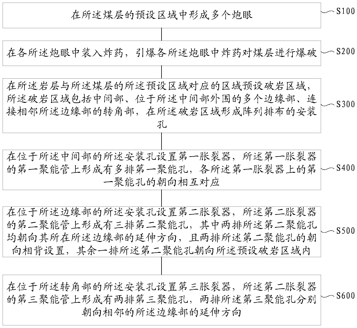
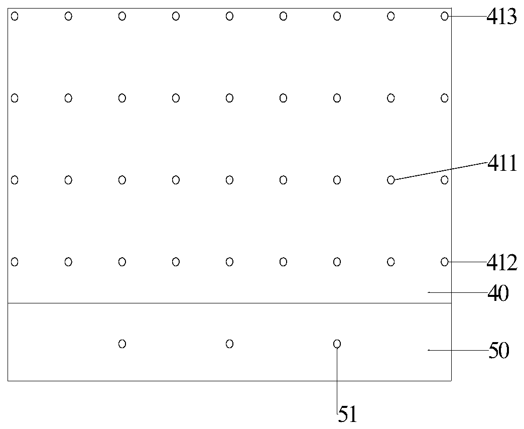
The invention relates to a geometric forming blasting method of a semi coal and rock roadway using an instantaneous spalling device. The geometric forming blasting method of the semi coal and rock roadway using the instantaneous spalling device comprises the steps that a plurality of blastholes are formed in a coal seam; explosives are loaded in each blasthole, the explosives in each blasthole aredetonated to blast the coal seam; mounting holes are formed in the area corresponding to the preset area of a rock layer and the coal seam in an array mode; first spalling device bodies are arrangedin the mounting holes in the middle, and a plurality of rows of first energy gathering holes are formed in energy gathering tubes of the first spalling device bodies, the orientations of the first energy gathering holes on each first spalling device body correspond to one another; second spalling device bodies are ararnged in the mounting holes on the edge parts, and three rows of second energy gathering holes are formed in energy gathering tubes of the second spalling device bodies, two rows of second energy gathering holes orient toward the extending direction of the edge parts where the second energy gathering holes are located, and the remaining row of second energy gathering holes orient toward a preset rock breaking area; third spalling device bodies are arranged on the mounting holes on the corner parts, and two rows of third energy gathering holes are formed in energy gathering tubes of the third spalling device bodies, and the third energy gathering holes separately orient toward the extending direction of adjacent edge parts.

Description

technical field [0001] The present disclosure relates to the technical field of technical mining, in particular, to a method for geometrically forming blasting of semi-coal and rock roadways by using an instantaneous expander. Background technique [0002] In my country's production mines, the proportion of semi-coal and rock roadways is increasing. At present, the blasting technology is mostly used in the excavation of semi-coal and rocky tunnels, but the following problems mainly exist in the blasting tunneling: difficulty in forming the tunnel, serious damage to the surrounding rock, resulting in waste of support equipment, poor construction conditions for the tunneling face; approval of explosives It is relatively difficult, which leads to a relatively slow excavation speed, which seriously affects the production succession of the working face; the energy of the explosive explosion is difficult to control, and the rock will be broken when excavating the rock formation, a...

Claims


Application Information

Patent Timeline
IPC IPC(8): F42D1/08F42D3/04
CPCF42D1/08F42D3/04
Inventor 何满潮郭山张权
Owner 何满潮
Learn More