Stable locating and punching device

A punching device and stable technology, applied in metal processing and other directions, can solve the problems of insufficient punching accuracy and low efficiency, and achieve the effects of ingenious structure, long service life, and improved accuracy and accuracy

Inactive Publication Date: 2018-06-01
重庆龙冠机械制造有限公司
View PDF0 Cites 1 Cited by
  • Summary
  • Abstract
  • Description
  • Claims
  • Application Information

AI Technical Summary

Problems solved by technology

[0004] In order to solve the above technical problems, the present invention provides a stable positioning punching de...

Method used


Image

  • Stable locating and punching device
  • Stable locating and punching device

Examples


Embodiment Construction

[0016] In order to enable those skilled in the art to better understand the technical solutions of the present invention, the present invention will be described in detail below in conjunction with the accompanying drawings and specific embodiments.

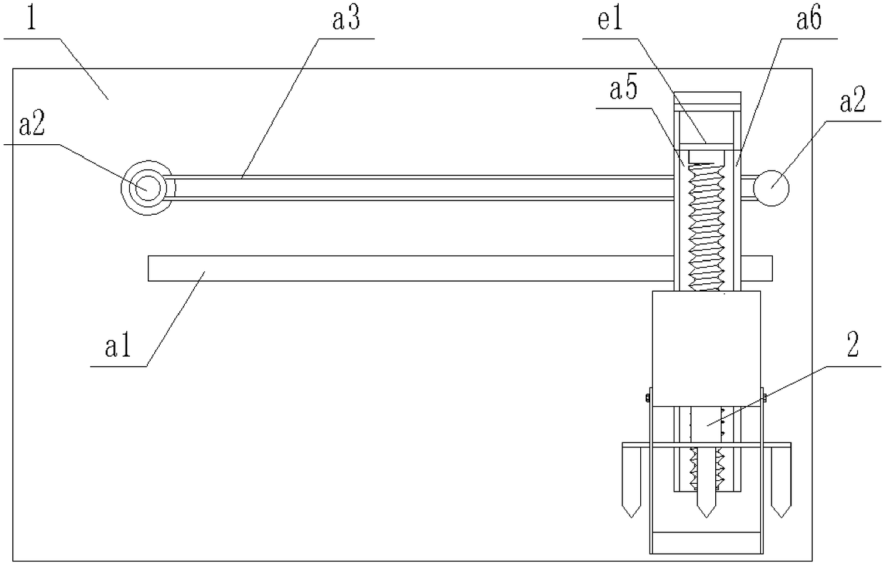
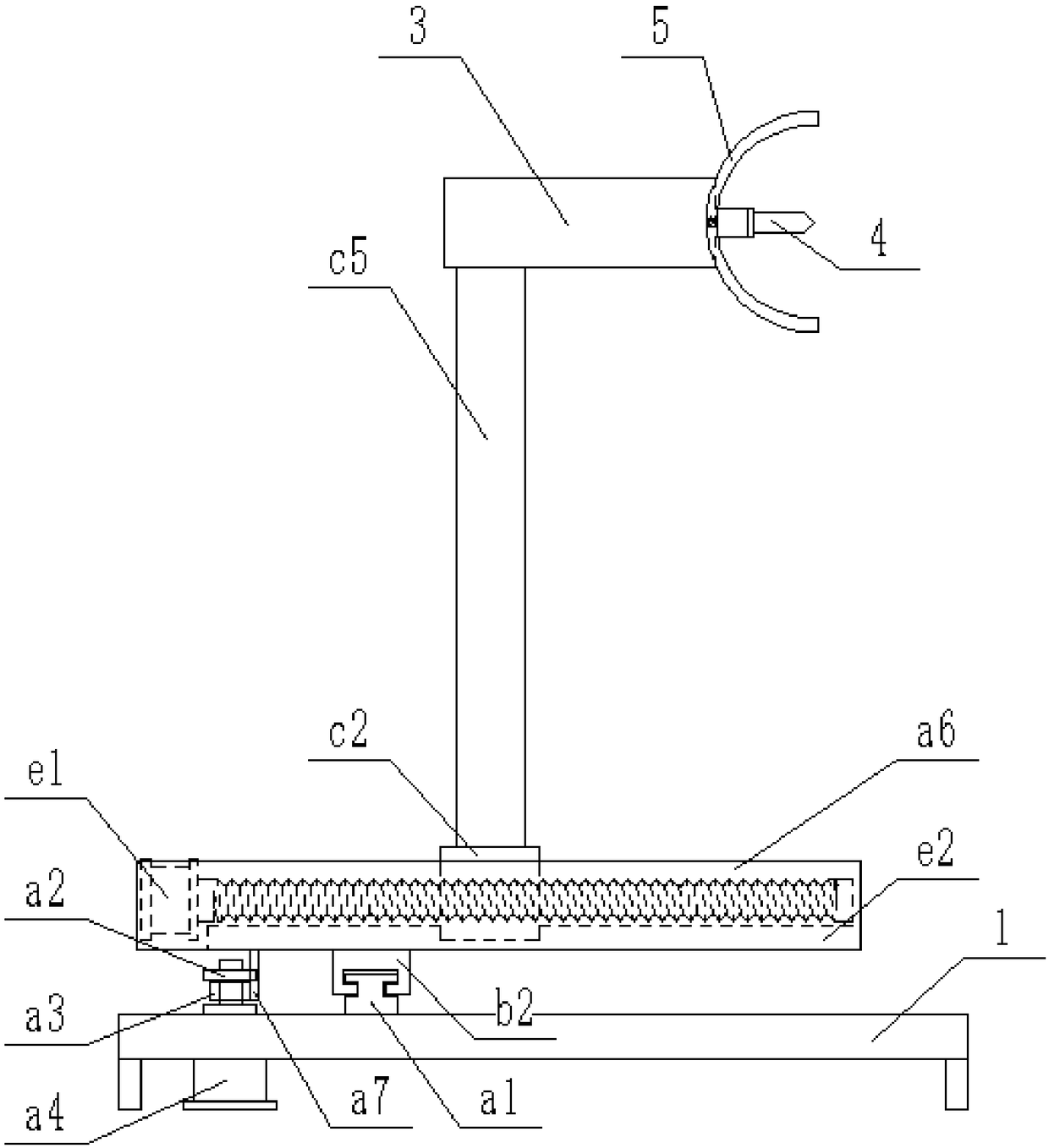
[0017] Such as figure 1 with figure 2 As shown, a stable positioning punching device includes a base 1 and a horizontally arranged perforating knife 2, the base 1 is provided with an X-direction pushing mechanism, and the base 1 on one side of the X-direction pushing mechanism is provided with There is a Y-direction pushing mechanism, and the Y-direction pushing mechanism is connected with the perforating knife 2 through a support rod;

[0018] The X-direction pushing mechanism includes an X-direction slide rail a1, on which a knife rest seat is slidably installed, and the knife rest seat is driven by a driving part to slide linearly on the X-direction slide rail a1; the drive part includes At least two first transmission whee...


PUM


Abstract

The invention discloses a stable locating and punching device. The stable locating and punching device comprises a base and a perforating knife. An X-direction push mechanism is arranged on the base.The base on one side of the X-direction push mechanism is equipped with a Y-direction push mechanism. The Y-direction push mechanism is connected with the perforating knife through a support rod. TheX-direction push mechanism comprises an X-direction slide rail. A knife rest seat is slidably installed on the X-direction slide rail. The knife rest seat is driven by a drive part to linearly slide along the X-direction slide rail. The drive part comprises at least two first delivery wheels installed on the base. The first delivery wheels are provided with a same X-direction conveyor belt in a sleeving manner. The X-direction conveyor belt is connected with the knife rest seat through a conveyor belt connecting part. Any first deliver wheel is connected with a driving motor. Compared with theprior art, the technical scheme is ingenious in structure, easy in operation, good in application effect and long in service lifetime. The height and rotary angles of a punch are adjusted in order tomeet requirements for hole depths and angles of inclinations of to-be-machined spare and accessory parts. Therefore, machining precision of the spare and accessory parts is effectively enhanced.

Description

technical field [0001] The invention relates to punching equipment, in particular to a stably positioned punching device. Background technique [0002] In today's product production and processing process, more and more products require a series of punching processes. The punching machine used to process spare parts is equipped with pliers to hold and move the processed parts on the surface of the table. spare parts. These pliers are mounted on a horizontally indexed datum bar in such a way that the position of these pliers is determined according to the size of the machined parts and to suit different needs, and during the punching operation, carried on the machine tool Punches will not interfere with these pliers. [0003] The indexing rod can be moved in two dimensions on the working plane of the punch so that the plate, still held by the pliers, is presented to the mechanical tool carried by the punch, so that it is possible to execute the command and control of each p...

Claims


Application Information

Patent Timeline
IPC IPC(8): B26F1/16B26D7/26
CPCB26F1/16B26D7/2628
Inventor 闫颖涛
Owner 重庆龙冠机械制造有限公司
Why Eureka
Try Eureka