Electronic lock clutch structure

An electronic lock and lock body technology, applied in the field of electronic locks, can solve problems such as inventory and inconvenient installation

Pending Publication Date: 2018-01-30
广东奥珀智慧家居股份有限公司
View PDF5 Cites 3 Cited by
  • Summary
  • Abstract
  • Description
  • Claims
  • Application Information

AI Technical Summary

Problems solved by technology

[0004] However, the user's door is divided into left and right, some are opened on the left; Therefore, inventory and installation are very inconvenient, so the designer designed a left and right clutch structure to solve the above problems

Method used


Image

  • Electronic lock clutch structure
  • Electronic lock clutch structure
  • Electronic lock clutch structure

Examples


Embodiment Construction

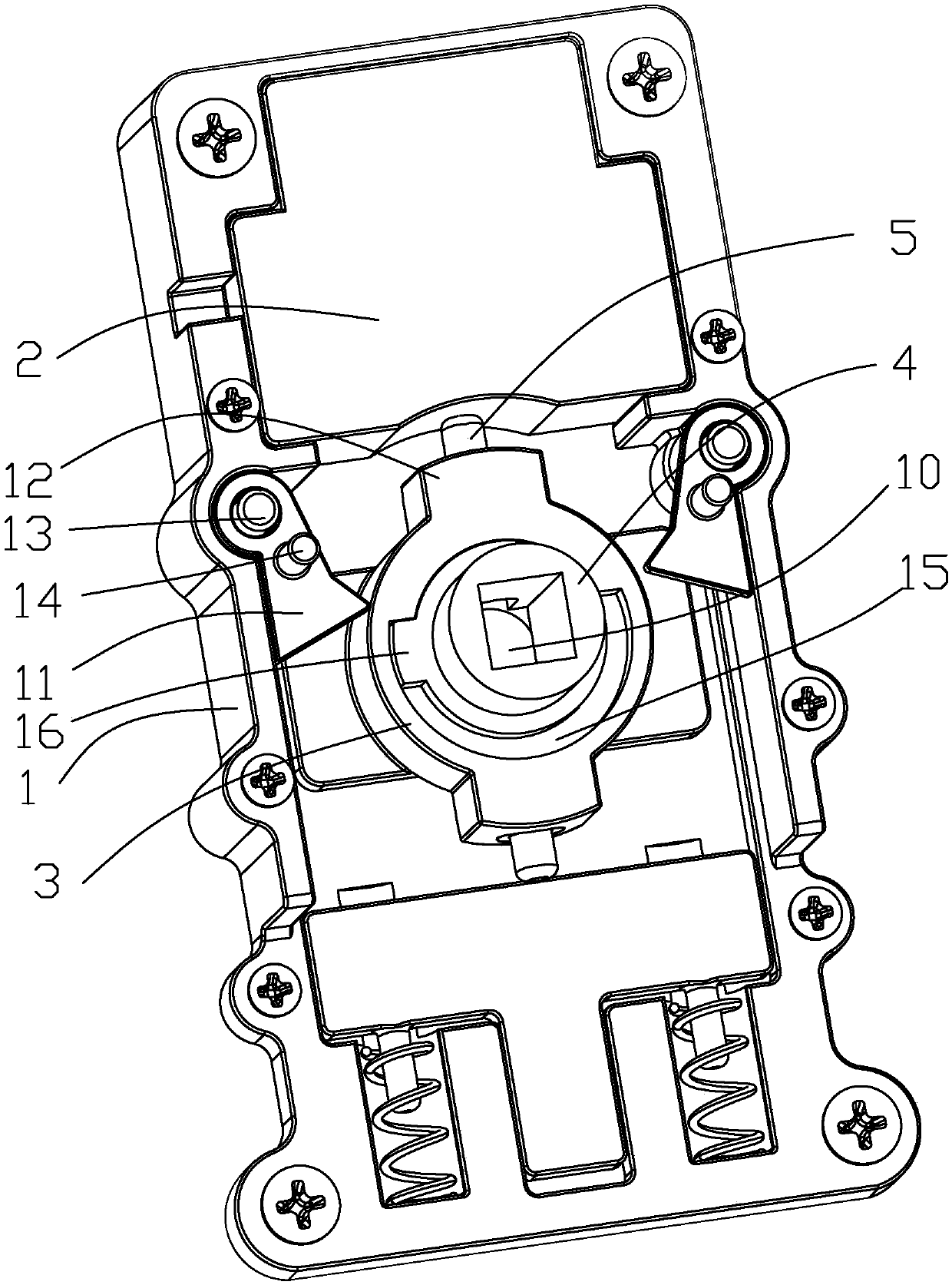
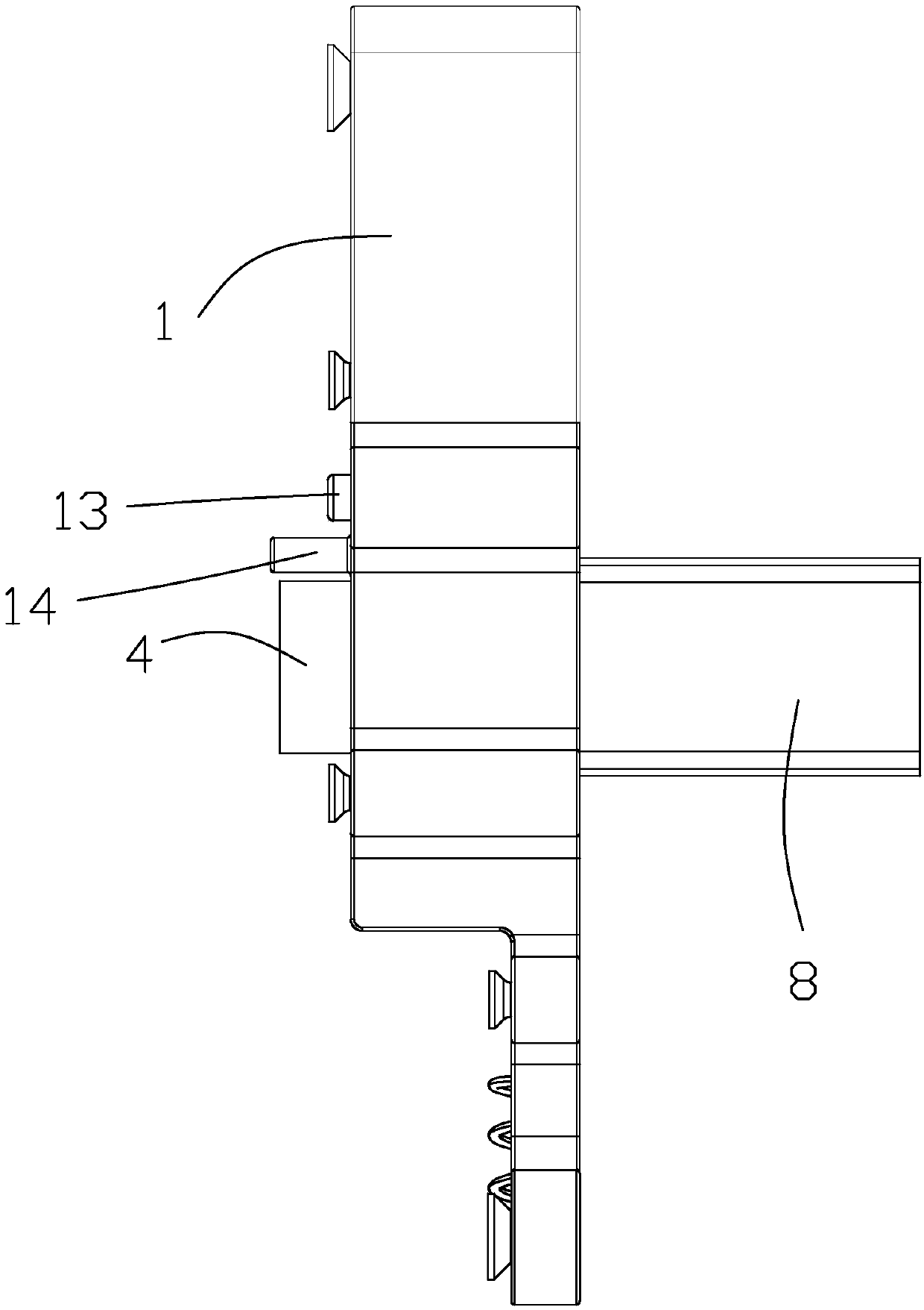
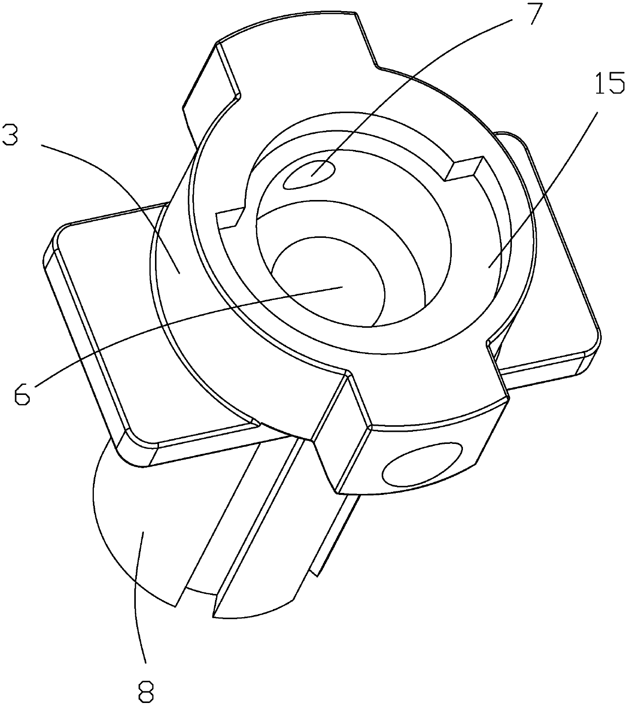
[0021] refer to Figure 1 to Figure 5 , the present invention discloses a clutch structure of an electronic lock, comprising a housing 1, a drive unit 2 is provided in the housing 1, a handle connecting part 3 capable of rotating in the housing 1, and a handle connecting part 3 capable of The rotating lock body connector 4, the limit mechanism that can limit the rotation range of the handle connector 3, the positioning pin 5 that can fix the handle connector 3 and the lock body connector 4 as one, and the drive unit 2 is an electromagnet , and the positioning pin 5 is made of a magnetic substance that repels or attracts the electromagnet. The housing 1 is provided with a lock hole, and the handle connector 3 is provided with a mounting hole 6 and an outer card that communicates with the mounting hole 6. hole 7 and the connecting rod 8 passing through the lock hole, the connecting rod 8 is fixed with the handle (not shown in the figure), the lock body connector 4 is located in ...


PUM


Abstract

The invention discloses an electronic lock clutch structure which comprises a shell. A driving unit, a handle connector, a lock connector, a limit mechanism and a positioning pin are arranged in the shell, a handle connector can rotate in the shell, the lock connector can rotate in the handle connector, the rotating range of the handle connector can be limited by the limit mechanism, the handle connector and the lock connector are integrally clamped and fixed by the positioning pin, a lock hole is formed in the shell, the handle connector is provided with a mounting hole, an outer clamping hole and a connecting rod, the outer clamping hole is communicated with the mounting hole, the connecting rod penetrates the lock hole, the lock connector is positioned in the mounting hole, an inner clamping hole and a square hole are formed in the lock connector, the driving unit can push the positioning pin to insert into the outer clamping hole and the inner clamping hole, the limit mechanism comprises two clamping pieces and two claming blocks, the clamping pieces can vertically move in the shell, the claming blocks are arranged on the handle connector, the clamping pieces can be clamped with the corresponding clamping blocks when moving to a clamping and stopping position, so that rotation of the handle connector is limited, a reset spring is arranged in the outer clamping hole, and thepositioning pin can reset by the aid of the reset spring.

Description

technical field [0001] The invention relates to an electronic lock, in particular to a clutch structure of the electronic lock. Background technique [0002] At present, door locks sold on the market can be roughly divided into two types, namely mechanical locks and electronic locks. The so-called mechanical lock refers to the mechanical connection between the various parts in the entire lock body. This type of door lock is widely used in life. But the shortcoming that it exists is that security is poor, mainly shows that the key of opening mechanical lock is easy to duplicate, yet the electronic key that is used to open electronic lock is difficult for imitation. The usual structure of the electronic lock unlocking device is: the motor drives the gear to rotate, drives the clutch device, and realizes unlocking through the clutch device. [0003] Electronic locks use non-mechanical keys such as passwords, random codes, two-dimensional codes, fingerprints, magnetic cards, r...

Claims


Application Information

Patent Timeline
Patent Type & Authority Applications(China)
IPC IPC(8): E05B47/06E05B3/00E05B49/00
Inventor 卢仕辉
Owner 广东奥珀智慧家居股份有限公司
Why Eureka
Try Eureka