Portable glass tank capping machine

A glass jar and capping machine technology, applied in the directions of bottle/container cap, bottle filling, screwless stopper, etc. Tightness, easy fixation

Active Publication Date: 2020-06-16
平邑经济开发区投资发展有限公司
View PDF8 Cites 5 Cited by
  • Summary
  • Abstract
  • Description
  • Claims
  • Application Information

AI Technical Summary

Problems solved by technology

[0003] Existing corks are placed on the mouth of glass jars by knocking to achieve capping. Because the cork is generally as big as the mouth of the jar or a little larger than the mouth of the jar, if the knocking force is small, the cork is difficult to remove. Press it into the mouth of the glass jar to cover it. If the knocking force is strong, the cork may overshoot and fall into the glass jar. At the same time, the glass jar may be broken. After all, glass jars are fragile.

Method used


Image

  • Portable glass tank capping machine
  • Portable glass tank capping machine
  • Portable glass tank capping machine

Examples


Embodiment 1

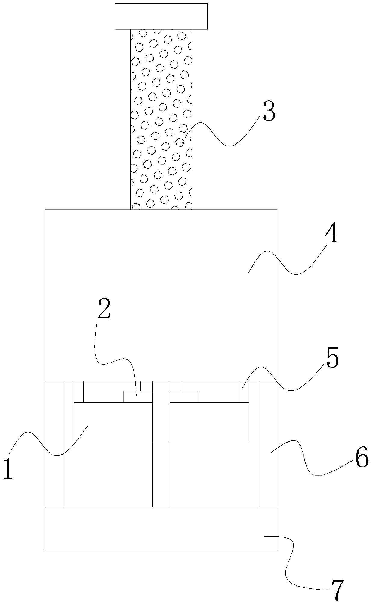
[0038] see figure 1 , the present invention provides a technical solution for a portable glass jar capping machine: its structure includes a cork clamping device 1, a hydraulic cylinder 2, an anti-skid handle 3, a support cylinder 4, an inner connecting rod 5, an outer connecting rod 6, a glass jar clamp Tightening device 7, the outer top center of the support tube 4 is vertically connected to the anti-slip handle 3, and the inner bottom is vertically connected to the hydraulic cylinder 2, the hydraulic cylinder 2 is located directly above the cork clamping device 1, and the cork clamping The four positive directions of the device 1 are connected with the support cylinder 4 through the inner connecting rod 5, and the glass jar clamping device 7 is arranged in parallel below the cork clamping device 1, and the glass jar clamping device 7 passes through four Equidistantly arranged outer connecting rods 6 are connected to the support cylinder 4;

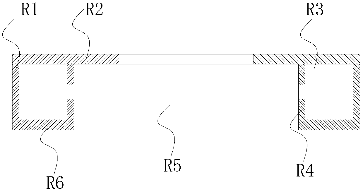
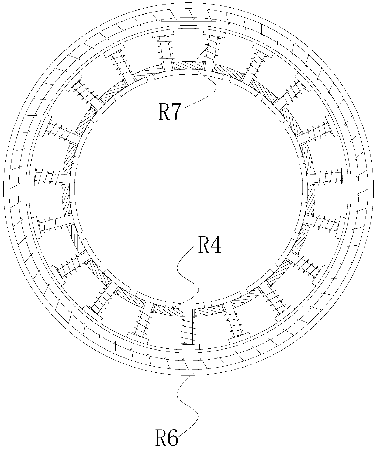
[0039] see Figure 2-3 The co...

Embodiment 2

[0045] see figure 1 , the present invention provides a technical solution for a portable glass jar capping machine: its structure includes a cork clamping device 1, a hydraulic cylinder 2, an anti-skid handle 3, a support cylinder 4, an inner connecting rod 5, an outer connecting rod 6, a glass jar clamp Tightening device 7, the outer top center of the support tube 4 is vertically connected to the anti-slip handle 3, and the inner bottom is vertically connected to the hydraulic cylinder 2, the hydraulic cylinder 2 is located directly above the cork clamping device 1, and the cork clamping The four positive directions of the device 1 are connected with the support cylinder 4 through the inner connecting rod 5, and the glass jar clamping device 7 is arranged in parallel below the cork clamping device 1, and the glass jar clamping device 7 passes through four Equidistantly arranged outer connecting rods 6 are connected to the support cylinder 4, and the aluminum ring R1 is arran...


PUM


Abstract

The invention discloses a portable glass tank capping machine. The structure of the portable glass tank capping machine comprises a wooden plug clamping and shrinking device, a hydraulic cylinder, ananti-skid handle, a supporting barrel, an inner connecting rod, an outer connecting rod and a glass tank clamping device, the outer top center of the supporting barrel is perpendicularly connected tothe anti-skid handle, the inner bottom of the supporting barrel is perpendicularly connected with the hydraulic cylinder, and the hydraulic cylinder is located over the wooden plug clamping and shrinking device. Compared with prior art, the portable glass tank capping machine has the beneficial effects that the novel portable glass tank capping machine is formed by combining the wooden plug clamping and shrinking device, the hydraulic cylinder, the anti-skid handle, the supporting barrel, the inner connecting rod, the outer connecting rod and the glass tank clamping device, the size is small,carrying is convenient, a glass tank is fixed through the suction cups, the wooden plug is clamped and shrunk in the mode that the wooden plug is clamped and shrunk, so that the diameter of the woodenplug is reduced, the wooden plug is pushed downwards through the hydraulic cylinder, the wooden plug can be conveniently, rapidly and stably plugged into a glass tank opening, the capping and plugging efficiency is greatly improved, capping and plugging are stable, and damage to the glass tank capping and plugging is effectively avoided.

Description

technical field [0001] The invention relates to the technical field of glass jar capping machinery, in particular to a portable glass jar capping machine. Background technique [0002] In the liquid filling industries such as pesticides, medicines, cosmetics, food, beverages, and wines, glass jars are used for food packaging, gift packaging, and pharmaceutical packaging. stamped. [0003] Existing corks are placed on the mouth of glass jars by knocking to achieve capping. Because the cork is generally as big as the mouth of the jar or a little larger than the mouth of the jar, if the knocking force is small, the cork is difficult to remove. Press it into the mouth of the glass jar to cover it. If the knocking force is strong, the cork may overshoot and fall into the glass jar. At the same time, the glass jar may be broken. After all, glass jars are fragile. Contents of the invention [0004] The main purpose of the present invention is to overcome the deficiencies of the...

Claims


Application Information

Patent Timeline
Patent Type & Authority Applications(China)
IPC IPC(8): B67B1/04
CPCB67B1/045
Inventor 英攀东
Owner 平邑经济开发区投资发展有限公司
Why Eureka
Try Eureka