Supercharge Your Innovation With Domain-Expert AI Agents!

Systems and methods for providing force vector compensated fan nozzles

A fan-shaped, arc-shaped technology used in the removal of contaminants from materials and equipment

Active Publication Date: 2020-06-16
CADENT
View PDF10 Cites 0 Cited by
  • Summary
  • Abstract
  • Description
  • Claims
  • Application Information

AI Technical Summary

Problems solved by technology

However, the above systems have not always been sufficiently successful in effectively removing contaminants in specific applications

Method used


Image

  • Systems and methods for providing force vector compensated fan nozzles
  • Systems and methods for providing force vector compensated fan nozzles
  • Systems and methods for providing force vector compensated fan nozzles

Examples


Embodiment Construction

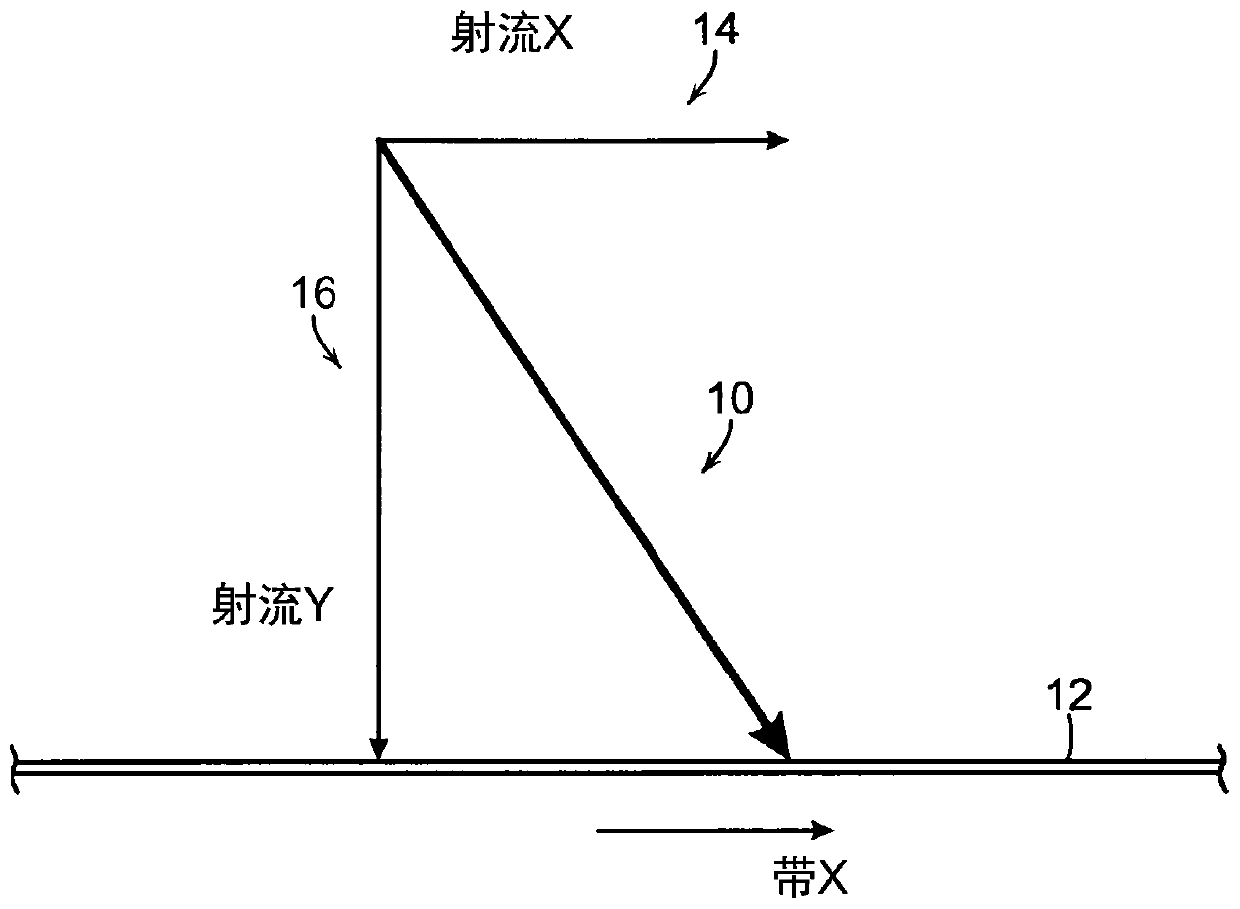
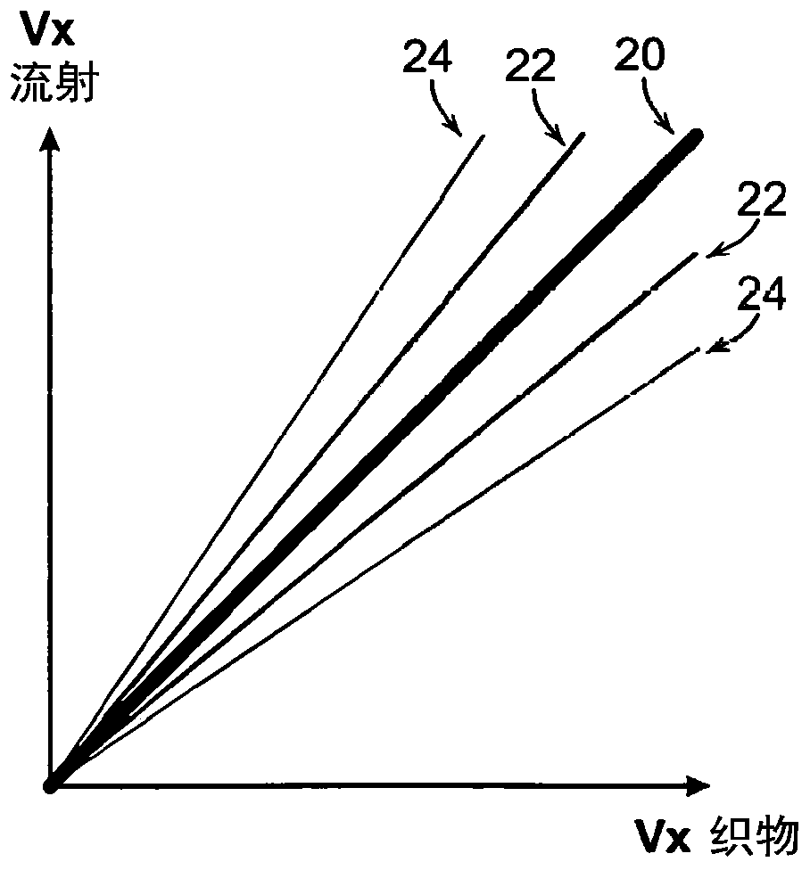
[0018] The geometry of the sprinkler / belt interaction is typically constructed in such a way as to provide the most efficient force vector intersection angle to provide the desired decontamination function. For penetration cleaning (pushing material through the belt), the system is typically set up so that the water spray X velocity vector value equals the belt X velocity value so that the Y force vector pushes the contaminant through the belt. The above content is in figure 1 , which shows a force vector 10 applied to the moving belt 12 , wherein the force vector 10 includes an X-direction component as shown in 14 and a Y-direction component as shown in 16 . Arrangements through penetration are generally well suited for jet nozzles because the impingement is essentially a single point per nozzle and only two axes are needed to determine the optimum impingement angle. The above content is in figure 2 , which shows at 20 that the force vector is maximized when the jet veloci...


PUM


Abstract

A method is disclosed of facilitating the removal of contaminates from a belt in a papermaking system. The method includes the step of providing a fluid in a shaped fan such that the interface betweenthe fluid and the belt is non-linear and at least generally forms the shape of an arc.

Description

[0001] This application claims priority to U.S. Provisional Application No. 62 / 526,105, filed June 28, 2017, which is incorporated herein by reference in its entirety. technical field [0002] The present invention relates generally to papermaking equipment and processes, and more particularly to the removal of contaminants from materials and equipment during the papermaking process. Background technique [0003] In the papermaking process, paper is conveyed through a paper machine by a plurality of belts known as wires in the forming section, felts in the press section and dryer fabrics in the drying section. These serpentines are filled and / or coated with various contaminants fed / carried by the paper. Removal of contaminants is necessary to maintain peak efficiency of the papermaking process. Typically a series of showers are used to remove contaminants from the conveyor belt. As used herein, the term belt refers to all conveyor fabrics regardless of the location of the ...

Claims


Application Information

Patent Timeline
IPC IPC(8): D21F1/32D21F1/34
CPCD21F1/32D21F1/34B08B3/022B08B2230/01B65G45/22D21F7/12D21H21/02
Inventor P·T·卡斯滕森
Owner CADENT
Features
  • R&D
  • Intellectual Property
  • Life Sciences
  • Materials
  • Tech Scout
  • Unparalleled Data Quality
  • Higher Quality Content
  • 60% Fewer Hallucinations
Learn More