A cavitation load-reducing rod structure for underwater vehicles

A technology for underwater vehicles and aircraft, applied in the direction of hull, ship construction, hull design, etc., can solve the problems of aircraft shell rupture, damage to the internal structure of the aircraft, failure of the aircraft to enter the water, etc., to reduce the wetted area Effect

Active Publication Date: 2022-03-15
NORTHWESTERN POLYTECHNICAL UNIV
View PDF10 Cites 0 Cited by
  • Summary
  • Abstract
  • Description
  • Claims
  • Application Information

AI Technical Summary

Problems solved by technology

[0003] Air-launched underwater vehicles face the problem of entering the water. The vehicle will be subjected to a huge impact load during the process of entering the water, which may cause the hull of the vehicle to break and destroy the internal structure of the vehicle. At the same time, it may affect the trajectory of the vehicle entering the water, making The aircraft failed to enter the water

Method used


Image

  • A cavitation load-reducing rod structure for underwater vehicles
  • A cavitation load-reducing rod structure for underwater vehicles

Examples


Embodiment Construction

[0023] The present invention will now be further described in conjunction with the embodiments and accompanying drawings:

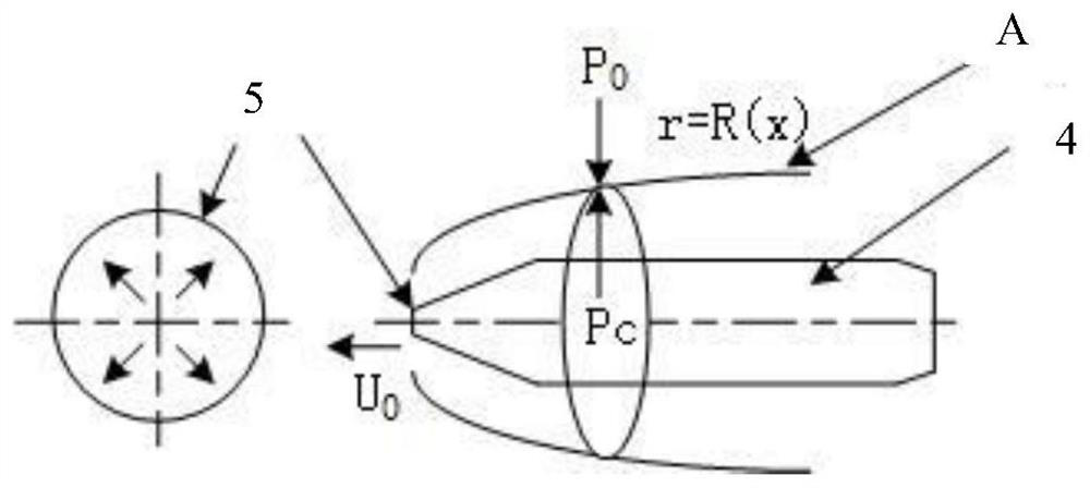
[0024] When the vehicle enters the water at a certain speed, under the action of the head cavitation, the surrounding water pressure P 0 There is a pressure drop process, when it drops to the internal pressure P of the cavity c When Δp=p 0 -p c , the vacuoles form agglomerates. Once this dynamic process reaches an equilibrium point, that is, the pressure values ​​of the two are equal, at this time r=R(x) r is the radius of the vacuoles, and x is the radial length of the vacuoles, satisfying Cavitation Continuity Boundary Condition: When the boundary is in a steady state, a natural supercavitation that is stable and smooth and envelops the entire projectile (except the head cavitation is in a wet state) is formed.

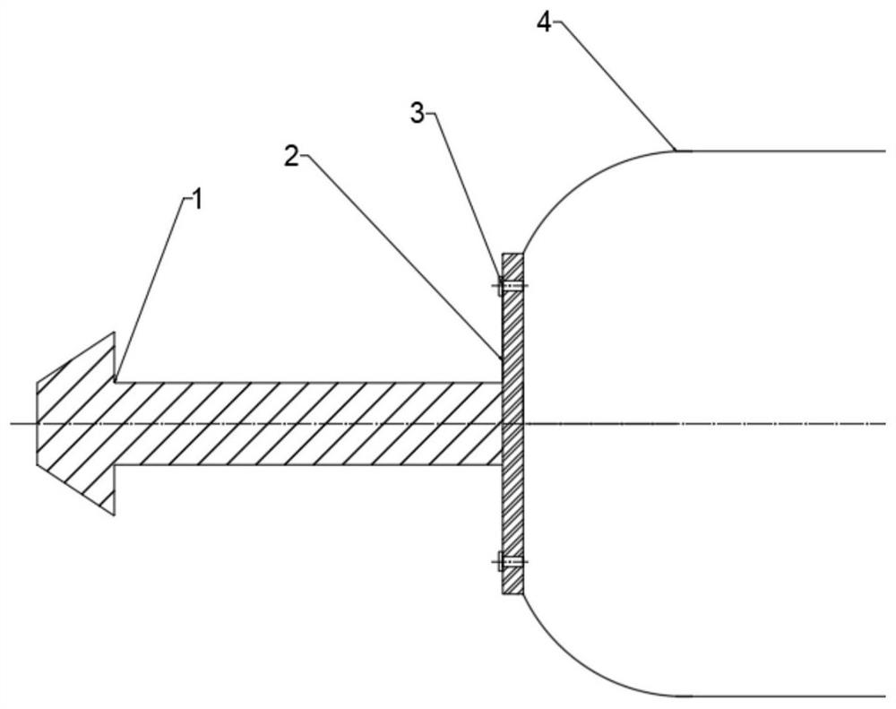
[0025] The water entry speed of the aircraft targeted by the present invention is relatively large, so the natural cavitation device can be...


PUM


Abstract

The invention relates to a structure of a cavitation load-reduction rod for an underwater vehicle which is put into water, which comprises a load-reduction rod, a positioning part and a connecting part. Among them, the load-reducing rod is composed of a cylindrical section and a circular table section. It plays the role of opening the cavitation when the aircraft enters the water, effectively reducing the wetted area of ​​the aircraft when entering the water. By adjusting the length of the rod body and the length of the cone, the size of the generated cavitation can be controlled. , so that it completely wraps the aircraft, and designs different sizes of load-reducing rods for different water entry conditions and aircraft. The positioning part is a disc, the load-reducing rod body is welded on the front end of the positioning part disc, and the rear end face of the positioning part disc is attached to the aircraft head as a supporting surface. The connecting part is an explosive bolt, which combines the positioning part with the aircraft. After the aircraft completes the water entry process, the bolt is detonated at an appropriate time to separate the load-reducing rod from the aircraft, without affecting the hydrodynamic performance of the aircraft and the underwater trajectory.

Description

technical field [0001] The invention belongs to the field of underwater load drop devices for aircraft, relates to a cavitation load drop rod structure for placing underwater vehicles into water, and in particular relates to a method for adding cavitation load drop bars to the head of the aircraft. The craft enters the water safely and reliably. Background technique [0002] The underwater vehicle can be launched in the air by means of airdrop, rocket-assisted flight, etc., or by surface ships or underwater submarines. Among them, the aerial launch can make the underwater vehicle quickly reach the operating sea area to carry out work, saving energy and energy. search time. [0003] Aerial-launched underwater vehicles are faced with the problem of entering water. The vehicle will be subjected to a huge impact load during the process of entering the water, which may cause the rupture of the vehicle shell and damage the internal structure of the vehicle. The vehicle failed to...

Claims


Application Information

Patent Timeline
Patent Type & Authority Patents(China)
IPC IPC(8): B63B1/38
CPCB63B1/38B63B2001/382Y02T70/10
Inventor 潘光高兴甫宋保维施瑶曹永辉黄桥高
Owner NORTHWESTERN POLYTECHNICAL UNIV
Why Eureka
Try Eureka