Rotor pump and assembly method thereof

An assembly method and technology of rotor pumps, which are applied to rotary piston pumps, pumps, components of pumping devices for elastic fluids, etc., can solve problems such as increased labor intensity, high processing costs, and rotor jamming, and achieve reduction Labor intensity, reduce processing cost, and avoid the effect of excessive clearance

Active Publication Date: 2022-04-12
FAW JIEFANG AUTOMOTIVE CO
View PDF5 Cites 0 Cited by
  • Summary
  • Abstract
  • Description
  • Claims
  • Application Information

AI Technical Summary

Problems solved by technology

[0004] However, an interference fit is adopted between the bearing on the main transmission shaft and the housing, and an interference fit is also adopted between the bearing on the driven shaft and the housing; High machining accuracy, so that the effect of interference fit is better, so as to ensure that the main transmission shaft and the driven shaft have a better parallelism during the rotation process, and the processing cost is relatively high; on the other hand, when the rotor pump is assembled Finally, the gap between the two rotors is too small, and the rotor is stuck; or the gap between the two rotors is too large, so that the transmission efficiency is low; and the bearing and the housing are both interference fit, Partial adjustment is not possible, and the rotor pump needs to be disassembled and then reassembled, which is cumbersome and labor-intensive

Method used


Image

  • Rotor pump and assembly method thereof
  • Rotor pump and assembly method thereof
  • Rotor pump and assembly method thereof

Examples


Embodiment 1

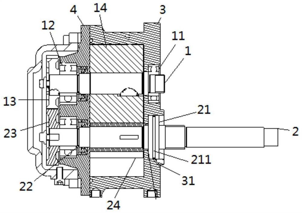
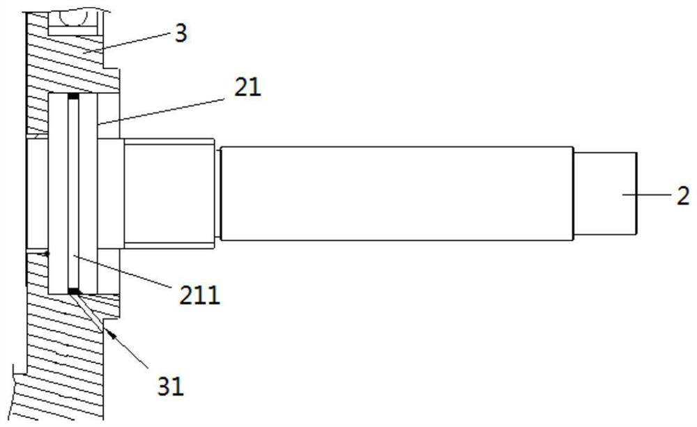
[0041] This embodiment proposes a rotor pump for transporting items to be transported, such as figure 1 As shown, the rotor pump includes a housing 3 , a first transmission shaft 1 and a second transmission shaft 2 . Wherein, one end of the first transmission shaft 1 is pierced with a first bearing 11, and the first bearing 11 is arranged in a first bearing seat on the casing 3, and a first rotor 14 is also arranged on the first transmission shaft 1; The two transmission shafts 2 are driven in parallel with the first transmission shaft 1, and the second transmission shaft 2 is meshed with the first transmission shaft 1 for transmission. One end of the second transmission shaft 2 is pierced with a second bearing 21, and the second bearing 21 is arranged on In the second bearing seat on the casing 3 , a second rotor 24 is also provided on the second transmission shaft 2 , and the second rotor 24 and the first rotor 14 can rotate synchronously and in opposite directions.

[0042...

Embodiment 2

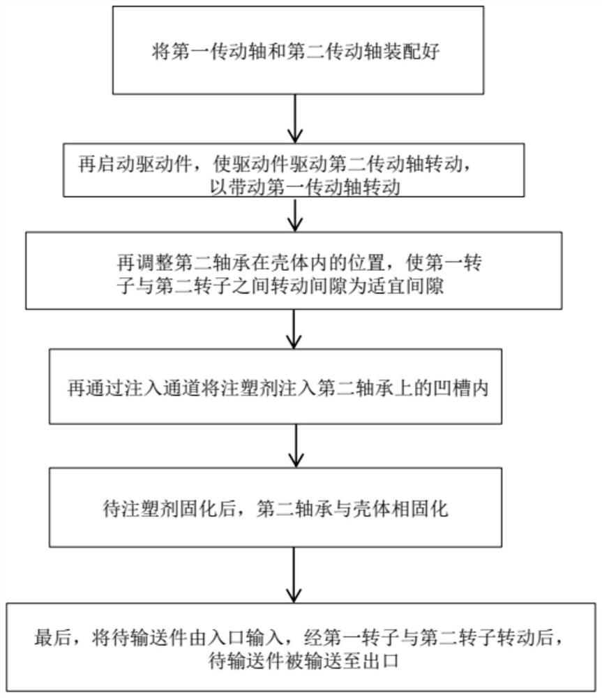
[0048] In this embodiment, a method for assembling the rotor pump is proposed, which is used for assembling the rotor pump in the first embodiment. Specifically, the assembly method of the rotor pump includes the following steps: Step 10: respectively assembling the first transmission shaft 1 and the second transmission shaft 2 on the casing 3, so that the first transmission shaft 1 and the second transmission shaft 2 are meshed for transmission; Step 20: Drive the second transmission shaft 2 to rotate to drive the first transmission shaft 1 to rotate, so that the first rotor 14 and the second rotor 24 rotate in opposite directions, and adjust the position of the second bearing 21 relative to the housing 3, To adjust the rotation gap between the first rotor 14 and the second rotor 24 to an appropriate gap; Step 30: inject the injection molding agent into the injection molding groove 211, and wait for the injection molding agent to solidify to solidify the second bearing 21 rela...


PUM


Abstract

The invention discloses a rotor pump and an assembly method thereof, belonging to the technical field of rotor pumps. The rotor pump includes a casing; a first transmission shaft, one end of which is provided with a first bearing, and the first bearing is arranged in a first bearing seat on the casing, and the first transmission shaft is provided with a first Rotor; second transmission shaft, which is parallel to the first transmission shaft, the second transmission shaft is provided with a second rotor, one end of the second transmission shaft is provided with a second bearing, and the second bearing In the second bearing seat provided on the housing, injection molding grooves are provided on the outer peripheral wall of the second bearing and / or on the upper ring of the inner peripheral wall of the second bearing seat for injection molding and containing injection molding agent. Its advantage is that it can adjust the rotation gap between the first rotor and the second rotor without disassembly, and at the same time keep the rotation gap between the first rotor and the second rotor unchanged during the rotation process .

Description

technical field [0001] The invention relates to the technical field of rotor pumps, in particular to a rotor pump and an assembly method thereof. Background technique [0002] The rotor pump refers to the pump that changes the working volume through the relative movement between the rotor and the pump body, thereby increasing the energy of the gas or liquid; the rotor of the rotor pump rotates without impact, with high speed, compact structure, and relatively small volume. Small, so when transporting gas or liquid, the rotor pump has incomparable advantages over other pumps. [0003] However, in the existing rotor pump, in order to make the main transmission shaft and the driven shaft keep parallel to each other during the rotation process, so that the rotation gap between the rotor on the main transmission shaft and the rotor on the driven shaft is not large. Angle deviation occurs to prevent the rotor on the main transmission shaft from colliding with the rotor on the dri...

Claims


Application Information

Patent Timeline
Patent Type & Authority Patents(China)
IPC IPC(8): F04C2/12F04C15/00F04C18/12F04C29/00
CPCF04C2/12F04C15/0076F04C18/12F04C29/0078F04C2230/601F04C2230/602F04C2240/50F04C2240/56F04C2240/60
Inventor 倪永成陈雷雷易正根梅赟栋徐世龙丁成
Owner FAW JIEFANG AUTOMOTIVE CO
Why Eureka
Try Eureka