Optical lens optical axis thermal stability testing device and method

An optical lens and thermal stability technology, applied in optical instrument testing, measuring devices, testing optical performance, etc., can solve the problems of thermal deformation of photodetectors, large measurement errors, changes in the position of imaging star points, etc., to eliminate test errors , The effect of the test process is easy

Active Publication Date: 2020-06-23
BEIJING INST OF CONTROL ENG
View PDF12 Cites 5 Cited by
  • Summary
  • Abstract
  • Description
  • Claims
  • Application Information

AI Technical Summary

Problems solved by technology

[0005] However, the conventional test method is for the overall measurement of the combination of lens and detector components. Under temperature changes, the position of the star point on the image surface of the detector changes. On the one hand, it can be caused by the change of the optical axis of the optical lens, on the other hand , the photodetector will also cause thermal deformation with temperature changes, which in turn will lead to changes in the position of the imaging star point
Therefore, the measurement results of the conventional method include the influence of the thermal deformation of the image plane of the detector on the change of the star point imaging position, which represents the overall thermal stability level of the assembly, not the characteristics of the optical lens itself, and the measurement error is relatively large

Method used


Image

  • Optical lens optical axis thermal stability testing device and method
  • Optical lens optical axis thermal stability testing device and method
  • Optical lens optical axis thermal stability testing device and method

Examples


Embodiment Construction

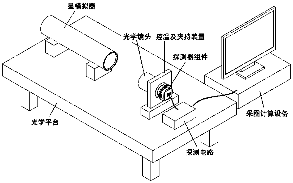
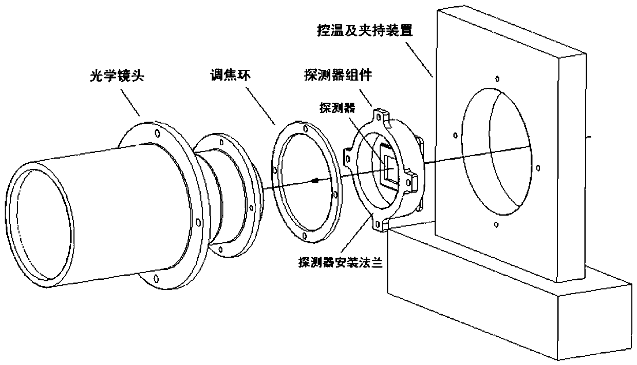
[0029] Such as figure 1 As shown, a test device for the thermal stability of the optical axis of an optical lens of the present invention includes an optical platform, a star simulator, an imaging assembly, a temperature control and clamping device, a detection circuit, and a drawing calculation device; the imaging assembly Including optical lens and detector components;

[0030] The optical platform provides a stable test environment as the basic support equipment for the test; the star simulator, imaging assembly, temperature control and clamping device are all placed on the optical platform during the test, and the star simulator and the optical lens are aligned in the axial direction and It is required that the light emitted by the star simulator can completely cover the entrance pupil of the optical lens; the star simulator simulates a star point at infinity as the detection target in the test; the light emitted by the star simulator forms an image on the detector compone...


PUM


Abstract

The invention discloses an optical lens optical axis thermal stability testing device and method. The device comprises an optical platform, a star simulator, an imaging assembly, a temperature controland clamping device, a detection circuit and image acquisition and calculation equipment. The imaging assembly comprises an optical lens and a detector assembly. The star simulator, the imaging assembly and the temperature control and clamping device are all arranged on the optical platform during testing; light emitted by the star simulator is imaged on a detector assembly in the imaging assembly; the temperature control and clamping device is used for clamping the imaging assembly, and a temperature change of the imaging assembly is controlled through an electric heating piece or an oil waypipeline facility arranged in the temperature control and clamping device; the optical lens in the imaging assembly is used as a tested unit in the test to converge target source light and image on the detector assembly; the detection circuit is connected with a detector assembly in the imaging assembly and is used for forming control and output of images; and the image acquisition and calculation equipment is connected with the detection circuit and is used for acquiring, recording, analyzing and calculating the images.

Description

technical field [0001] The invention relates to a test device and method for the thermal stability of the optical axis of an optical lens, belonging to the field of space star sensor test. Background technique [0002] The thermal drift of the space star sensor is the main source of its low-frequency error, and it is of great significance to enhance the thermal stability of the star sensor to improve its accuracy. The thermal stability of the star sensor can be further decomposed into the main optical-mechanical structure of the imaging link, such as optical lens, detector components, mechanical structure, etc. Among them, the thermal stability of the optical lens is particularly important, and its accurate measurement is the premise of improving the design of the optical lens and enhancing the thermal stability. [0003] The thermal stability of the optical axis of an optical lens refers to the ability of the optical axis of the optical lens to resist the influence of temp...

Claims


Application Information

Patent Timeline
Patent Type & Authority Applications(China)
IPC IPC(8): G01M11/02G01M11/04
CPCG01M11/0242G01M11/04
Inventor 隋杰武延鹏郑然张腾飞梁士通王晓燕钟俊李林
Owner BEIJING INST OF CONTROL ENG
Why Eureka
Try Eureka