Method for detecting different verification states through wireless radio frequency identification, locking and sealing device and equipment

A wireless radio frequency and radio frequency technology, applied in the direction of antenna support/installation device, antenna, antenna parts, etc., can solve the problems of complex structure of equipment and sealing device, cumbersome structure of conversion verification state, etc., and achieve simple structure and applicability Strong, simple effect of validating state transitions

Pending Publication Date: 2020-06-30
夏敬懿
View PDF0 Cites 1 Cited by
  • Summary
  • Abstract
  • Description
  • Claims
  • Application Information

AI Technical Summary

Problems solved by technology

For this reason, an object of the present invention is to propose a kind of detection method of radio frequency identification different verification state, aims to solve existing sealing device and equipment, when connecting different verification states that can be identified by radio frequency, equipment The internal structure of the lock and seal device is complicated, and the structure of the conversion verification state is relatively cumbersome technical problem

Method used


Image

  • Method for detecting different verification states through wireless radio frequency identification, locking and sealing device and equipment
  • Method for detecting different verification states through wireless radio frequency identification, locking and sealing device and equipment
  • Method for detecting different verification states through wireless radio frequency identification, locking and sealing device and equipment

Examples


Embodiment Construction

[0062] The following will clearly and completely describe the technical solutions in the embodiments of the present invention with reference to the accompanying drawings in the embodiments of the present invention. Obviously, the described embodiments are only part of the embodiments of the present invention, not all of them. Based on the embodiments of the present invention, all other embodiments obtained by persons of ordinary skill in the art without creative efforts fall within the protection scope of the present invention.

[0063] All directional indications (such as up, down, left, right, front, back...) in the embodiments of the present invention are only used to explain the relative positional relationship between the components in a certain posture (as shown in the accompanying drawings) , sports conditions, etc., if the specific posture changes, the directional indication also changes accordingly.

[0064] In the present invention, descriptions such as "first", "sec...


PUM


Abstract

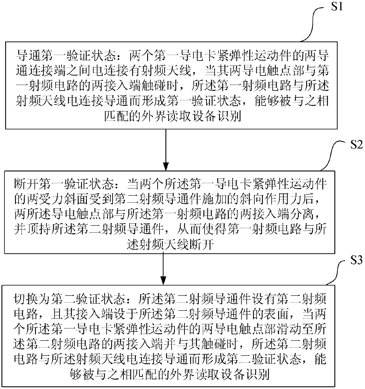
The invention discloses a method for detecting different verification states through wireless radio frequency identification, a locking and sealing device and equipment. The method comprises the stepsthat the first verification state is conducted, a radio frequency antenna is electrically connected between the two conduction connecting ends of the two first conductive clamping elastic moving parts in the first verification state, and when the two conductive contact parts of the first conductive clamping elastic moving parts are in contact with the two access ends of the first radio frequencycircuit, the first radio frequency circuit is electrically connected and conducted with the radio frequency antenna to form the first verification state; the first verification state is disconnected,and the second radio frequency conduction piece is located between the first radio frequency conduction piece and the two first conductive clamping elastic moving pieces; and when the two conductive contact parts are conducted with the second radio frequency circuit, a second verification state is formed. According to the technical scheme, circuits in the radio frequency antenna, the first radio frequency conduction piece and the second radio frequency conduction piece are connected and disconnected through the conductive clamping elastic moving piece, external read-write equipment matched with the radio frequency conduction pieces is used for reading, and then the detection method for switching between the first verification state and the second verification state is achieved.

Description

technical field [0001] The invention relates to the technical field of radio frequency identification, in particular to a detection method of different verification states of radio frequency identification, a sealing device and equipment applying the detection method of different verification states of radio frequency identification. Background technique [0002] At present, RFID technology is widely used in the storage, inventory and management of materials to achieve intelligent management. It does not require contact identification, can penetrate various media and read, and the reading speed is fast. The UHF RFID antenna is installed on the electronic device to receive or transmit wireless signals. Due to the existing sealing device and equipment, each verification state adopts a separate circuit structure, which can be identified by radio frequency when connected to different In the verification state, the internal structure of the equipment and the sealing device is com...

Claims


Application Information

Patent Timeline
Patent Type & Authority Applications(China)
IPC IPC(8): G06K7/10H01Q1/22H01Q1/50
CPCG06K7/10297H01Q1/2216H01Q1/2225H01Q1/50
Inventor 夏敬懿
Owner 夏敬懿
Why Eureka
Try Eureka