Wrong weft prevention control device of air-jet loom

An air-jet loom and control device technology, which is applied in looms, textiles, textiles and papermaking, etc., can solve the problems of high frictional resistance, weft pulling, weft insertion offset, etc. Resistance, the effect of improving stability

Active Publication Date: 2020-07-03
湖北金恒昌纺织有限公司
View PDF4 Cites 2 Cited by
  • Summary
  • Abstract
  • Description
  • Claims
  • Application Information

AI Technical Summary

Problems solved by technology

[0003] However, the existing weft insertion mechanism still adopts the traditional pulley structure as its thread feeding structure in the lead wire. Because the acceleration air pressure of the nozzle pulls the weft thread too fast, and the friction resistance of the traditional pulley structure is relatively large, it is often used in the thread lead process. The pulling of the weft thread causes the weft thread to break, causing the sequence of the weft thread to be disturbed in the air-jet weaving program, causing a series of wrong wefts in the air-jet weaving. In addition, the weft thread is prone to static electricity when the weft thread is fed when the weft is inserted and fed. When a large amount of static electricity accumulates in the weft insertion mechanism, it is easy to interfere with the weft insertion mechanism, causing the weft insertion to deviate, resulting in interference-type weft error

Method used


Image

  • Wrong weft prevention control device of air-jet loom
  • Wrong weft prevention control device of air-jet loom
  • Wrong weft prevention control device of air-jet loom

Examples


Embodiment Construction

[0021] The following will clearly and completely describe the technical solutions in the embodiments of the present invention with reference to the accompanying drawings in the embodiments of the present invention. Obviously, the described embodiments are only some, not all, embodiments of the present invention. Based on the embodiments of the present invention, all other embodiments obtained by persons of ordinary skill in the art without making creative efforts belong to the protection scope of the present invention.

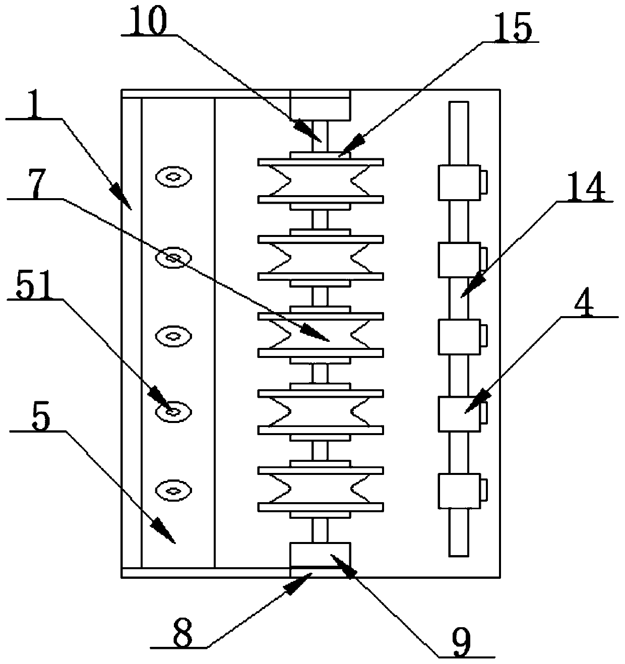
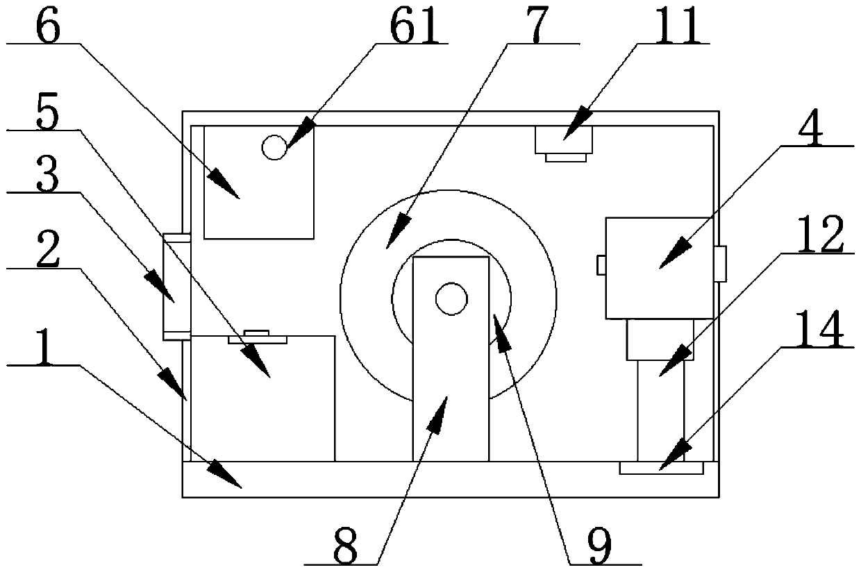
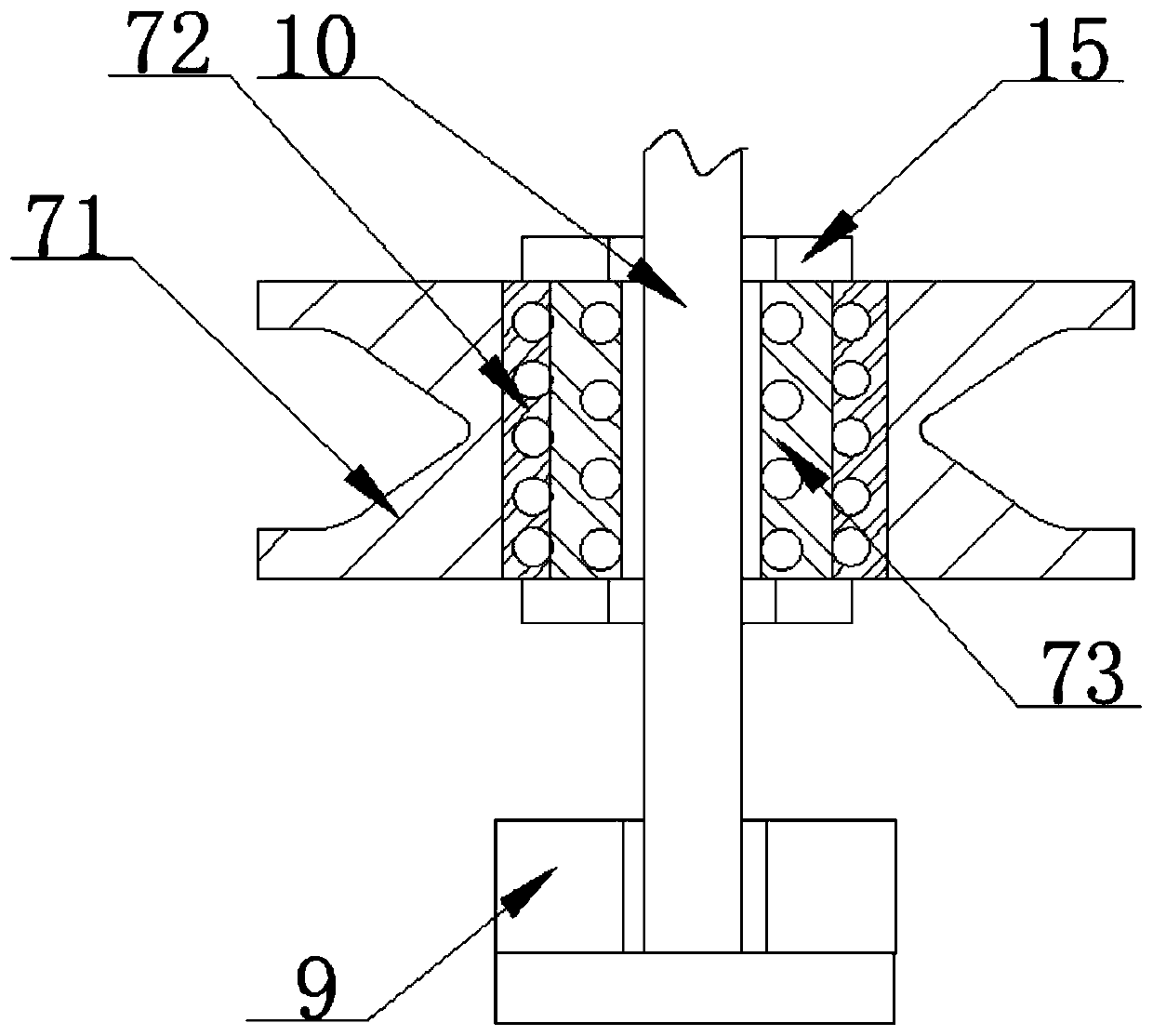
[0022] as attached Figure 1-4 An anti-wrong weft control device for an air-jet loom is shown, which includes an equipment installation side cover 1, a weft insertion box 2 and an auxiliary weft insertion main nozzle 4. One side of the weft insertion box 2 is provided with a thread feeding port 3, and the equipment installation side The inner side of the cover 1 is fixedly installed with an ultrasonic atomizing spray plate 5, and the inside of the weft inserti...


PUM


Abstract

The invention discloses a wrong weft prevention control device for an air-jet loom, and particularly relates to the field of air-jet looms. The wrong weft prevention control device comprises an equipment mounting side cover, a weft insertion box and an auxiliary weft insertion main nozzle, an ultrasonic atomization spray plate is mounted on the inner side of the equipment mounting side cover, an ultrasonic atomizer and a humidity sensor are fixedly mounted in the inner part of the weft insertion box, supporting clamping plates are fixedly installed at the upper end and the lower end of the inner side of the equipment mounting side cover, electromagnetic coils, vertical guide rods and floating guide wheels are installed on the inner sides of the supporting clamping plates, and permanent magnet rings are attached to the two sides of each floating guide wheel. According to the wrong weft prevention control device for the air-jet loom, by arranging a magnetic floating guide wheel structure, floating installation of a guide wheel is achieved through repulsion of like poles of magnetism, suspending the guide wheel is carried out to isolate friction connection between the guide wheel andthe surface of a supporting rod, friction of the guide wheel in the wire guiding process is prevented from hindering rotation of the guide wheel, and therefore guiding resistance to wefts is reduced,quick transmission of weft insertion of the nozzle can be adapted, wrong weft caused by weft breakage is prevented, and the stability of air-jet weaving is improved.

Description

technical field [0001] The invention relates to the technical field of air-jet looms, and more specifically, the invention is an anti-wrong weft control device for air-jet looms. Background technique [0002] With the continuous improvement of market demand, the emergence of multi-colored weaving technology puts forward higher requirements for air-jet looms. Air-jet looms are mainly composed of shedding mechanism, air weft insertion mechanism, weft beating mechanism, The weft yarn is drawn into the shed by using the flow of air and the characteristics of jet bunching. The weft insertion mechanism is the core mechanism of the air-jet loom. When the weft yarn is unwound from the weft feeder, the auxiliary main machine The main spray channel composed of the nozzle and the main nozzle is accelerated by the low pressure and put into the shed, and then flies over the shed under the traction of the relay nozzle to complete the weft insertion process. [0003] However, the existing...

Claims


Application Information

Patent Timeline
Patent Type & Authority Applications(China)
IPC IPC(8): D03D47/30D03J1/04
CPCD03D47/3066D03J1/04
Inventor 姚东鑫姚於
Owner 湖北金恒昌纺织有限公司
Why Eureka
Try Eureka