Ecological floating bed for ecological environment protection and construction method

An environmental protection and ecological floating bed technology, applied in chemical instruments and methods, botanical equipment and methods, applications, etc., can solve problems such as troublesome installation, and achieve the effects of fast assembly, simple structure and high stability

Active Publication Date: 2020-07-10
新昌县澄聚农业科技有限公司
View PDF6 Cites 2 Cited by
  • Summary
  • Abstract
  • Description
  • Claims
  • Application Information

AI Technical Summary

Problems solved by technology

[0003] However, this kind of ecological floating bed in the prior art needs to be installed with the help of a boat when it is built, and the installation is relatively troublesome.

Method used


Image

  • Ecological floating bed for ecological environment protection and construction method
  • Ecological floating bed for ecological environment protection and construction method
  • Ecological floating bed for ecological environment protection and construction method

Examples


Embodiment 1

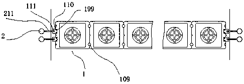
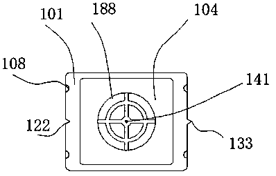
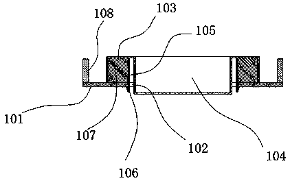
[0041] refer to Figure 1 to Figure 5 The shown ecological floating bed for ecological environment protection includes a plurality of modules 1 that can be combined adjacently, and anchor rods 2 installed on the river bank; A side groove 102 is vertically penetrated at the bottom plate 101, and a detachable box body 103 is installed on the top of the bottom plate 101. The middle part of the box body 103 is sunken to form a planting groove 104. The planting groove The lower end of 104 passes through described square groove 102 downwards, and the inner top position of described box body 103 is provided with a plurality of fixed rods 105, and the side of described fixed rods 105 away from described planting groove 104 is injection-molded to form a Hook 106, the fixed rod 105 passes through the square groove 102 downwards, the hook 106 hooks the bottom plate 101, at this time the box body 103 is fixed on the bottom plate 101, the fixed A gap of 8 mm to 12 mm is left between the r...

Embodiment 2

[0045] refer to Figure 7 As shown, the end of the pull rope 211 passing through the pull hole 111 is covered with a weight tube 121, and a first screw 131 is fitted between the balance tube 121 and the pull rope 211. The counterweight tube 121 sinks to the river bed, and the diameter of the breeding tube 121 is larger than the aperture of the traction hole 111; Disengagement with the traction hole 111.

Embodiment 3

[0047] refer to figure 2 with Figure 7 As shown, an insertion hole 141 is provided at the bottom axis of the planting groove 104 , and the planting device 3 is fitted through the insertion hole 141 .

[0048] The planting device 3 includes a planting cup 301, a movable rod 302 is arranged at the bottom axis of the planting cup 301, and an upper limit sleeve 303 is set on the movable rod 302, and the upper limit sleeve 303 and the A second screw 304 is fitted between the movable rods 302, a rubber washer 355 is arranged at the bottom of the upper limit sleeve 303, a counterweight rod 305 is threadedly connected to the lower end of the movable rod 302, and the lower end of the counterweight rod 305 A counterweight 306 is provided, the movable rod 302 passes through the socket 141, the upper limit sleeve 303 is limited at the bottom of the planting groove 104; The overflow hole 333 is provided with a sponge base 334 inside the planting cup 301. When in use, the overflow hole ...


PUM


Abstract

The invention discloses an ecological floating bed for ecological environment protection and a construction method. The ecological floating bed comprises a plurality of modules which can be adjacentlycombined, and anchor rods mounted at river banks. Each module comprises a bottom plate, a square-opening groove is vertically formed in the middle of the bottom plate in a penetrating mode, a movablydetachable box body is installed above the bottom plate, and a planting groove is formed after the middle of the box body is concaved downwards. The product can be assembled on the bank without launching operation, so that the operation is safer and more convenient.

Description

technical field [0001] The invention relates to an ecological floating bed for ecological environment protection and a construction method thereof. Background technique [0002] Ecological floating island, also known as artificial floating bed, ecological floating bed, etc. It is a kind of artificial floating island, aiming at eutrophic water quality, using the principle of ecological engineering to degrade the content of COD, nitrogen and phosphorus in the water. It takes aquatic plants as the main body, uses the principle of soilless cultivation technology, uses polymer materials as the carrier and substrate, applies the symbiotic relationship between species, makes full use of the water body space niche and nutrient niche, so as to establish an efficient artificial ecosystem for Reduce the pollution load in water bodies. It can greatly improve the transparency of the water body, and at the same time, the water quality index has also been effectively improved, especially...

Claims


Application Information

Patent Timeline
Patent Type & Authority Applications(China)
IPC IPC(8): C02F3/32A01G9/02A01G31/02
CPCA01G9/027A01G31/02C02F3/32C02F2203/006Y02P60/21
Inventor 李军
Owner 新昌县澄聚农业科技有限公司
Why Eureka
Try Eureka