Pollution source area detection method and system for delineating LNAPLs in aeration zone based on ERT and IP

A detection method and vadose zone technology, applied in radio wave measurement systems, electric/magnetic exploration, measurement devices, etc., can solve problems such as ambiguity

Active Publication Date: 2020-07-10
SHANDONG UNIV
View PDF9 Cites 4 Cited by
  • Summary
  • Abstract
  • Description
  • Claims
  • Application Information

AI Technical Summary

Problems solved by technology

[0004] In view of the deficiencies in the prior art, the purpose of the present invention is to provide a method and system for detecting pollution source areas of LNAPLs in the vadose zone based on ERT and IP delineation, which solves the problem of ERT in delineating the scope of the LNAPLs pollution source area in the vadose zone. The ambiguity of the problem provides a reliable basis for the precise location of LNAPLs pollution source areas

Method used


Image

  • Pollution source area detection method and system for delineating LNAPLs in aeration zone based on ERT and IP
  • Pollution source area detection method and system for delineating LNAPLs in aeration zone based on ERT and IP
  • Pollution source area detection method and system for delineating LNAPLs in aeration zone based on ERT and IP

Examples


Embodiment 1

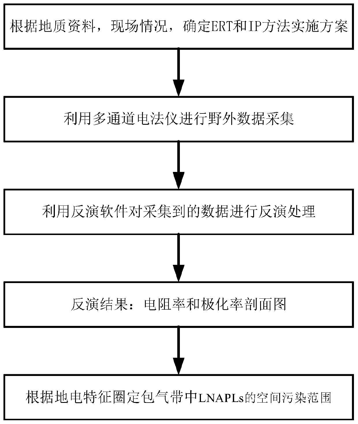
[0037] Attached below figure 1 The present invention is described in detail, specifically, as follows:

[0038] This embodiment provides a method for detecting pollution source areas based on ERT and IP to delineate LNAPLs in the vadose zone. Since the geophysical prospecting technology is a fast, non-invasive and non-destructive non-destructive testing technology, no damage is caused to the detected target. Intrusive destruction, and has the advantages of large detection range (horizontal and depth range), fast speed and high accuracy; while ERT and IP technology belong to the electrical branch of geophysical methods. ERT and IP technology are based on the differences in conductivity of rock, soil, and water in underground polluted areas to study the distribution of conduction current under the action of artificially applied stable current. The entire survey line can be exposed on the ground to the underground pollution situation, and the location of the pollution source are...

Embodiment 2

[0060] This embodiment provides a pollution source area detection system for delineating LNAPLs in the vadose zone based on ERT and IP, including:

[0061] The wiring mode determination module is used to determine the wiring mode of ERT and IP detection;

[0062] Data collection module, used to collect ERT and IP data of the same survey line;

[0063] The data processing module is used for data preprocessing and data inversion, and obtains resistivity and polarizability profiles;

[0064] The suspected pollution area delineation module is used to delineate the suspected pollution area according to the inversion results.

Embodiment 3

[0066] This embodiment provides an electronic device, including a memory, a processor, and a computer program stored on the memory and operable on the processor. When the processor executes the program, the ERT-based and IP detection method for delineating pollution source areas of LNAPLs in the vadose zone.


PUM


Abstract

The invention discloses a pollution source area detection method and method for delineating LNAPLs in aeration zone based on ERT and IP. According to the technical scheme, the method comprises the steps of determining an ERT and IP detection wiring mode; collecting ERT data and IP data of the same measuring line according to the wiring condition; carrying out data preprocessing and data inversionto obtain resistivity and polarizability profile maps; and delineating a suspected pollution area according to an inversion result. According to the method, the problem of fuzziness of the ERT in delineating the range of the LNAPLs pollution source area in the aeration zone is solved, and a reliable basis is provided for accurate positioning of the LNAPLs pollution source area.

Description

technical field [0001] The invention relates to the field of detection of polluted groundwater, in particular to a method and system for detecting pollution source areas of LNAPLs in a vadose zone based on ERT and IP delineation. Background technique [0002] With the rapid development of social economy, especially the emergence of a large number of industrial parks, outdated waste water treatment technology and leakage of small and medium-sized enterprises have caused groundwater and surface water pollution around the site. Groundwater pollution is spreading from point source pollution and strip pollution to planar pollution, penetrating from shallow to deep, and the degree and intensity of pollution are also increasing. The investigation of groundwater pollution in contaminated sites has become particularly critical. [0003] The traditional survey of polluted sites mostly uses a certain percentage of direct drilling and sampling analysis to obtain the pollution situation...

Claims


Application Information

Patent Timeline
Patent Type & Authority Applications(China)
IPC IPC(8): G01N27/04G01V3/10
CPCG01N27/041G01V3/101
Inventor 胡开友毛德强董艳辉夏腾宋瑞超赵瑞珏王亚洵孟健刘正达
Owner SHANDONG UNIV
Why Eureka
Try Eureka