
Improvement method for maximizing life cycle in wireless sensor network and terminal

A wireless sensor network and life cycle technology, applied in the field of wireless sensing, can solve the problems of long total link, reduced network life, and inability to transmit, so as to avoid detours, improve network life, and avoid power waste.

Active Publication Date: 2020-07-10
FUZHOU INSTITUE OF TECH
View PDF7 Cites 0 Cited by
  • Summary
  • Abstract
  • Description
  • Claims
  • Application Information

AI Technical Summary

Problems solved by technology

[0004] (1) It is easy to form a long chain in the late stage of chain formation. If a node dies, the reconstruction of the link will affect data collection;
[0005] (2) When the number of nodes is large, the total link formed is longer, and the transmission delay from both ends of the chain to the head of the chain is longer;
[0006] (3) Take turns acting as the chain head, causing the nodes far away from the base station to die too quickly
[0008] (1), only the shortest distance between nodes is considered, and the selection towards the sink direction is not considered;
[0009] (2) On the actual sensing node, the power control of the sensing node has only a few fixed levels, and the transmission cannot be carried out according to the theoretical shortest distance. Therefore, using the theoretical shortest distance transmission cannot effectively save energy consumption
[0010] Due to the existence of these two types of problems, unnecessary transmission paths are added, and the energy of each node transmission is not fully utilized, thus greatly reducing the network life.

Method used


Image

  • Improvement method for maximizing life cycle in wireless sensor network and terminal
  • Improvement method for maximizing life cycle in wireless sensor network and terminal
  • Improvement method for maximizing life cycle in wireless sensor network and terminal

Examples


Embodiment 1

[0084] Please refer to Figure 1 to Figure 7 , Embodiment 1 of the present invention is:

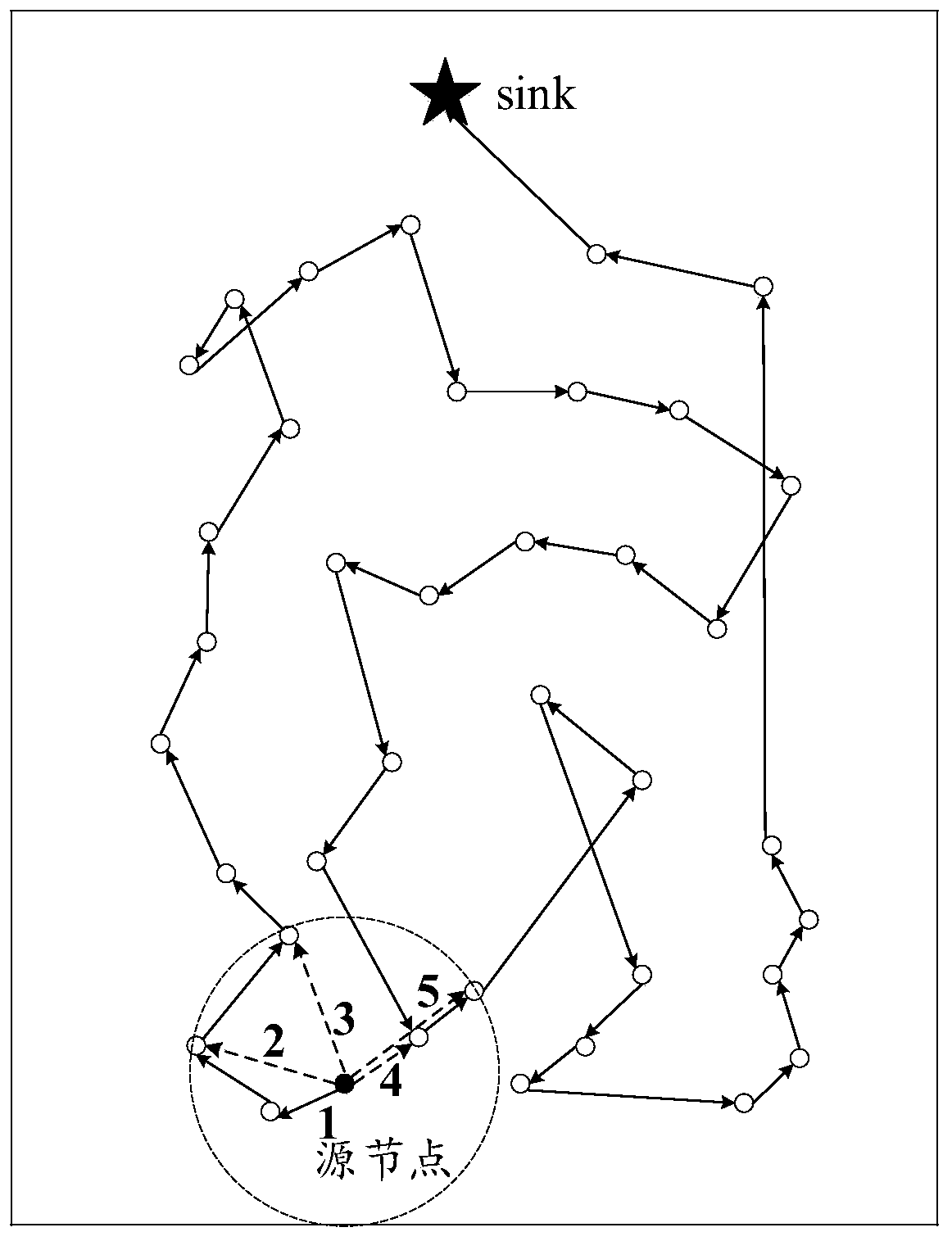
[0085] Before this example, if figure 2 As shown, the solid dot is the source node, also known as the source node. The path transmitted according to the PEGASIS protocol is shown by the solid line, and there are obviously "detours" and excessively long links. If it is transmitted according to a fixed distance, three paths 2, 3, and 5 may appear. Obviously, the path numbered 2 is the worst; if only the transmission direction is considered, there may be three paths 3, 4, and 5. Obviously, from From the perspective of maximizing energy utilization, the path numbered 3 or 5 is optimal. Therefore, only considering the transmission distance or only the transmission direction cannot effectively prolong the life of the network.

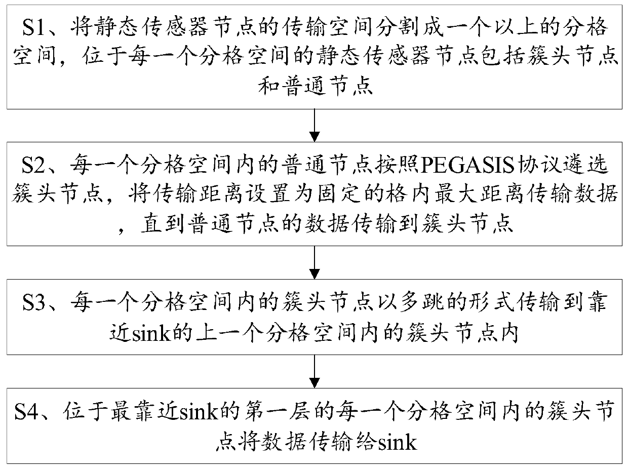
[0086] while this example image 3 The improved method for maximizing the life cycle in the shown wireless sensor network includes steps:

[0087] S1. Divide the ...

Embodiment 2

[0138] Please refer to Figure 8 , the second embodiment of the present invention is:

[0139] The improved terminal 1 that maximizes the life cycle in the wireless sensor network includes a memory 3, a processor 2, and a computer program stored on the memory 3 and operable on the processor 2, and the above-mentioned embodiments are realized when the processor 2 executes the computer program One step.

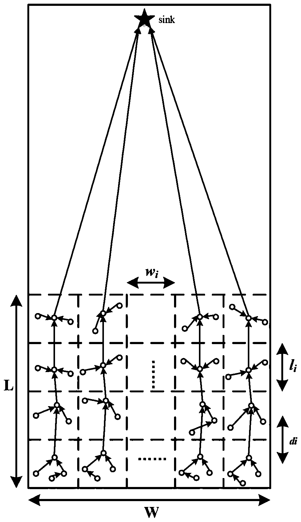
[0140] In summary, the improved method and terminal for maximizing the life cycle in wireless sensor networks provided by the present invention divide the transmission space of static sensor nodes into more than one grid space, wherein each cluster in each grid space The head node is transmitted to the cluster head node in the previous grid space close to the sink in the form of multi-hops, so that the transmission between nodes is constantly close to the sink to avoid the problem of detours; ordinary nodes in each grid space Select the cluster head node according to the PEGA...


PUM


Abstract

The invention discloses an improved method for maximizing the life cycle in a wireless sensor network and a terminal, and the method comprises the steps: dividing a transmission space of a static sensor node into more than one grid space, and the static sensor node located in each grid space comprising a cluster head node and a common node; selecting a cluster head node by a common node in each partition space according to a PEGASIS protocol, and setting the transmission distance as the maximum distance transmission data in a fixed partition until the data of the common node is transmitted tothe cluster head node; transmitting the cluster head node in each partition space to the cluster head node in the previous partition space close to the sink in a multi-hop mode; and the cluster head node located in each grid space of the first layer closest to the sink transmitting the data to the sink. According to the invention, the shortest path of data transmission towards sink is ensured, andthe transmission power between nodes can be effectively utilized, so that the network service life of the wireless sensor network is prolonged.

Description

technical field [0001] The invention relates to the field of wireless sensor technology, in particular to an improved method and a terminal for maximizing the life cycle in a wireless sensor network. Background technique [0002] With the continuous development of AI and AIOT technology, its application in smart city, smart medical care, smart agriculture, industry 4.0, smart home and smart education is becoming more and more extensive and in-depth. Wireless sensor network is the key communication technology to realize these technologies, and the network life of wireless sensor network determines the survival time of the whole system. Due to the difference and diversity of the environment, the lifetime of the nodes distributed in the wireless sensor network is determined by their battery energy. [0003] The PEGASIS (Power-Efficient Gathering in Sensor Information Systems) protocol is an improved protocol based on the LEACH (Low-Energy Adaptive Clustering Hierarchy) algorit...

Claims


Application Information

Patent Timeline
Patent Type & Authority Applications(China)
IPC IPC(8): H04W40/02H04W40/08H04W40/22H04W84/18
CPCH04W40/02H04W40/08H04W40/22H04W84/18Y02D30/70
Inventor 王琨余志民饶绪黎李妹
Owner FUZHOU INSTITUE OF TECH
Learn More