High-order SH guided wave imaging detection method and system for rail bottom cracks of steel rail

A technology for imaging detection and rail bottom, which is applied in measuring devices, processing response signals of detection, and analyzing solids using sonic/ultrasonic/infrasonic waves, which can solve the problem of inability to achieve efficient online detection of rail bottom cracks

Active Publication Date: 2020-07-17
NANCHANG HANGKONG UNIVERSITY +1
View PDF11 Cites 12 Cited by
  • Summary
  • Abstract
  • Description
  • Claims
  • Application Information

AI Technical Summary

Problems solved by technology

[0005] The invention provides a high-order SH guided wave imaging detection method and system for rail bottom cracks to solve the problem that the efficient online detection of rail bottom cracks cannot be realized in the prior art

Method used


Image

  • High-order SH guided wave imaging detection method and system for rail bottom cracks of steel rail
  • High-order SH guided wave imaging detection method and system for rail bottom cracks of steel rail
  • High-order SH guided wave imaging detection method and system for rail bottom cracks of steel rail

Examples


Embodiment 1

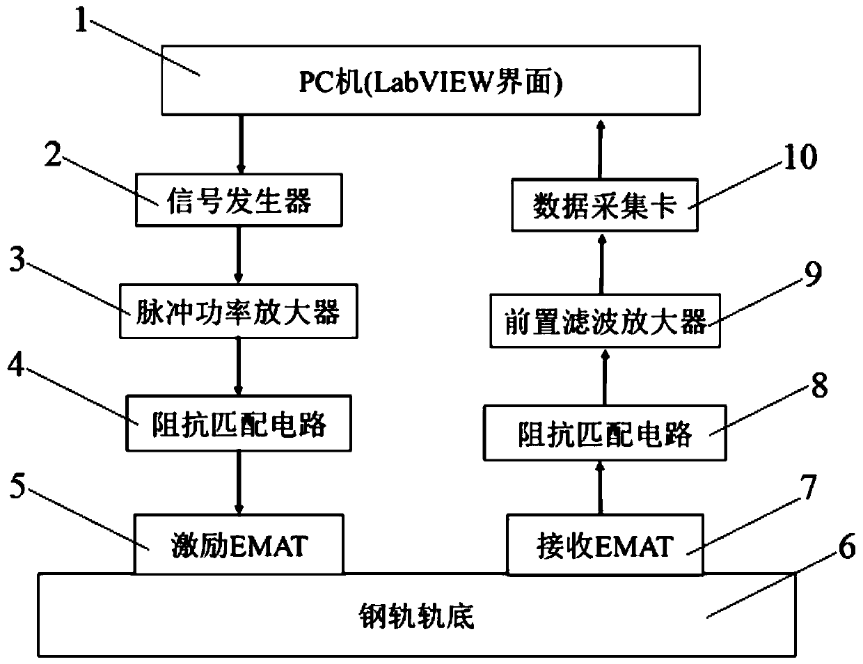
[0071] Such as figure 1 and Figure 5 As shown, this embodiment provides a high-order SH guided wave imaging detection system for rail bottom cracks, including a PC 1, a signal generator 2, a pulse power amplifier 3, a first impedance matching circuit 4, an electromagnetic ultrasonic SH guided wave excitation probe (exciting EMAT) 5; also includes electromagnetic ultrasonic SH guided wave receiving probe (receiving EMAT) 7, the second impedance matching circuit 8, pre-filter amplifier 9, data acquisition card 10 connected in sequence, the data Acquisition card 10 is also connected with described PC machine 1;

[0072] The signal generator 2 is used to receive the excitation command of the PC 1 and generate a sinusoidal pulse train current;

[0073] The pulse power amplifier 3 is used to amplify the sinusoidal pulse train current generated by the signal generator 2, and transmit it to the electromagnetic ultrasonic SH guided wave excitation probe 5 through the first impedance...

Embodiment 2

[0106] This embodiment provides a high-order SH guided wave imaging detection method for rail bottom cracks, including:

[0107] An electromagnetic ultrasonic SH guided wave excitation probe and an electromagnetic ultrasonic SH guided wave receiving probe are arranged at intervals on the bottom surface of the rail to be tested;

[0108] A sinusoidal pulse train current that can excite SH guided waves from the bottom of the rail is fed into the electromagnetic ultrasonic SH guided wave excitation probe;

[0109] The electromagnetic ultrasonic SH guide wave receiving probe receives the reflected echo and transmits the signal to the PC to obtain a set of detection echo signals;

[0110] Keep the distance between the electromagnetic ultrasonic SH guided wave excitation probe and the electromagnetic ultrasonic SH guided wave receiving probe unchanged, and move the two along the length of the rail bottom to be measured at a preset step length, and repeat the above steps to obtain mu...


PUM

PropertyMeasurementUnit
widthaaaaaaaaaa
lengthaaaaaaaaaa

Abstract

The invention discloses a high-order SH guided wave imaging detection method and system for rail bottom cracks of a steel rail. The method comprises the following steps of introducing sinusoidal pulsestring current into an electromagnetic ultrasonic SH guided wave excitation probe to excite an SH guided wave at the rail bottom of the steel rail, enabling the electromagnetic ultrasonic SH guided wave receiving probe to receive the reflection echo to obtain a detection echo signal, keeping the distance between the electromagnetic ultrasonic SH guided wave excitation probe and the receiving probe unchanged, moving along the to-be-detected length direction of the rail bottom of the steel rail at a preset step length, and acquiring a plurality of groups of detection echo signals, performing synchronous extrusion wavelet transform processing on each group of detection echo signals, and extracting high-order SH guided wave time domain signals to obtain multiple groups of high-order SH guidedwave time domain signals, performing B scanning imaging on the obtained multiple groups of high-order SH guided wave time domain signals, and obtaining a steel rail bottom defect imaging graph. High-order SH guided waves have the advantages of high resolution, high defect detection sensitivity and the like, and small cracks can also be visually recognized; the position and the size of the crack can be visually recognized, and the method is suitable for in-service nondestructive testing.

Description

technical field [0001] The invention relates to the technical field of crack detection, in particular to a high-order SH guided wave imaging detection method and system for rail bottom cracks. Background technique [0002] With the rapid development of my country's high-speed rail, the speed of trains has aggravated the damage to the rails. Due to the high-speed running of the train on the rails, the rails are constantly worn in the horizontal and vertical directions. The dynamic effect of the train makes the bottom of the rail easy to crack and break, which poses a major hidden danger to driving safety. Since the rail bottom is fixed on the sleepers, and the surface of the rail bottom is covered by sand and ballast, the traditional detection method combining shear wave and longitudinal wave can only be used for the detection of the rail head, but cannot detect the rail bottom. New methods are urgently needed for rail bottom detection, and the development of ultrasonic gui...

Claims


Application Information

Patent Timeline
Patent Type & Authority Applications(China)
IPC IPC(8): G01N29/06G01N29/44
CPCG01N29/069G01N29/44G01N2291/0234G01N2291/2623
Inventor 卢超胡松涛石文泽陈果陈尧陈振华吴锐钟芳桃席欢
Owner NANCHANG HANGKONG UNIVERSITY
Why Eureka
Try Eureka