
Electromechanical device with high protective property

An electromechanical equipment and protective technology, which is applied in the field of electromechanical equipment with high protection, can solve the problems of rainwater entering the interior of the power distribution cabinet, no protection for cooling holes, short circuit of the power distribution cabinet, etc., to improve fluency and protection High, the effect of protecting the cooling holes

Active Publication Date: 2020-07-24
宁波科创助手科技服务有限公司
View PDF11 Cites 0 Cited by
  • Summary
  • Abstract
  • Description
  • Claims
  • Application Information

AI Technical Summary

Problems solved by technology

[0004] Aiming at the problems existing in the prior art, the present invention provides an electromechanical device with high protection, which has the advantages of protecting heat dissipation holes and avoiding accidental touch, and solves the problem that dogs often appear in the equipment after installation of the existing power distribution cabinet. The function of drainage on the surface of the power distribution cabinet is likely to cause a short circuit in the power distribution cabinet. At the same time, the cooling holes have no protective function, which may easily cause rainwater to enter the interior of the power distribution cabinet through the cooling holes.

Method used


Image

  • Electromechanical device with high protective property
  • Electromechanical device with high protective property
  • Electromechanical device with high protective property

Examples


Embodiment Construction

[0031] In order to further understand the content, characteristics and effects of the present invention, the following embodiments are exemplified and described in detail below with the accompanying drawings.

[0032] The structure of the present invention will be described in detail below with reference to the accompanying drawings.

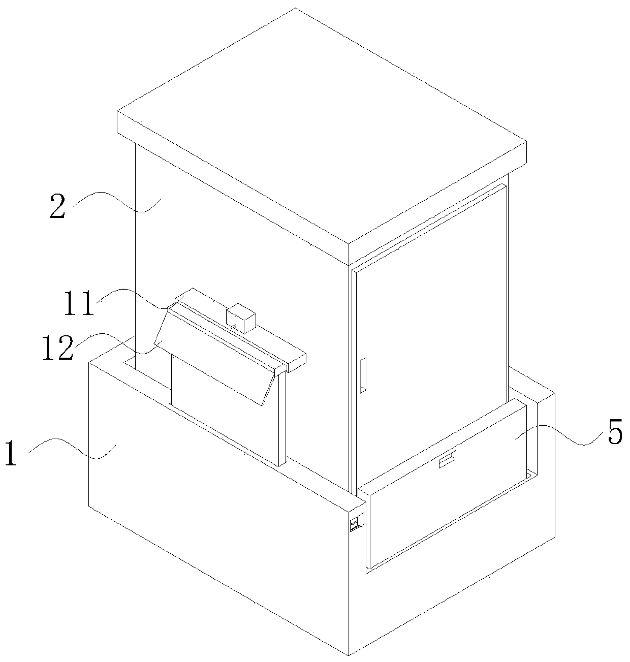
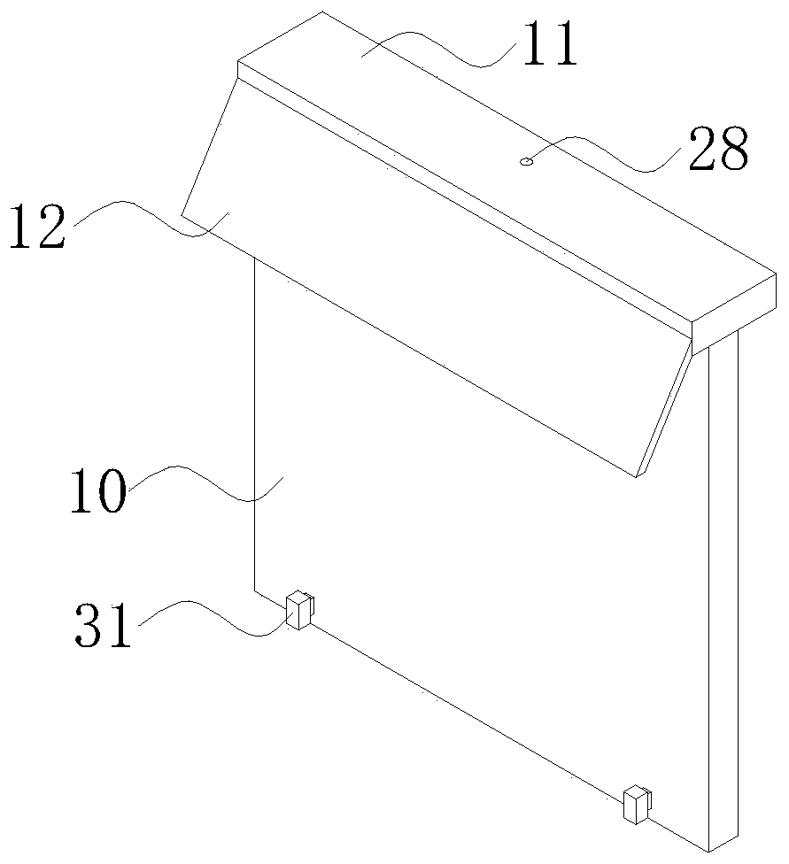
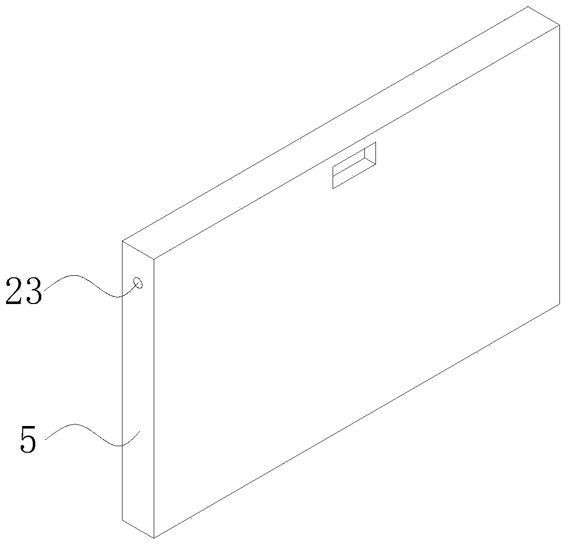
[0033] like Figure 1 to Figure 8 As shown, an electromechanical device with high protection provided by the embodiment of the present invention includes a mounting shell 1, the inner cavity of the mounting shell 1 is movably connected to an organic body 2, the bottom of the body 2 is provided with a mounting seat 3, and the top of the mounting shell 1 is provided with a mounting seat 3. The front side is provided with a movable groove 4, the inner cavity of the movable groove 4 is movably connected with a baffle plate 5, the left and right sides of the bottom of the baffle plate 5 are movably connected with a stabilizing mechanism 6, and a mova...


PUM


Abstract

The invention discloses an electromechanical device with a high protective property. The device comprises an installation shell, and an inner cavity of the installation shell is movably connected witha machine body. In the invention, through cooperative usage of heat dissipation holes, an inclined plate, a moving plate, a moving block, a baffle plate, a stabilizing mechanism, a clamping mechanismand a limiting mechanism, the stabilizing mechanism is used so that the baffle plate can be kept stable during adjustment; the clamping mechanism is used so that the position of the moving block canbe fixed; a user can conveniently adjust the inclined plate and the movable plate to protect the heat dissipation holes; the limiting mechanism is used so that the position of the baffle plate can befixed; a phenomenon that the machine body is mistakenly touched is avoided; the safety of the machine body is improved; and the problems that after an existing power distribution cabinet is installed,dogs often defecate on the surface of the device so that the phenomenon of short circuit of the power distribution cabinet is easily caused, and meanwhile rainwater easily enters the power distribution cabinet through the heat dissipation holes due to a fact that the heat dissipation holes do not have a protection function are solved.

Description

technical field [0001] The invention belongs to the technical field of electromechanical equipment, and in particular relates to an electromechanical equipment with high protection. Background technique [0002] Power distribution cabinets are divided into power distribution cabinets, lighting distribution cabinets, and metering cabinets. They are the final equipment of the power distribution system. Power distribution cabinets are the general name of motor control centers. Power distribution cabinets are used in situations where the load is relatively scattered and the circuits are less. , The motor control center is used for the occasions where the load is concentrated and there are many circuits. They distribute the electric energy of a certain circuit of the upper-level power distribution equipment to the nearby load, and this level of equipment should provide protection, monitoring and control for the load. [0003] The power distribution cabinet is widely used, and it ...

Claims


Application Information

Patent Timeline
Patent Type & Authority Applications(China)
IPC IPC(8): H05K5/02
CPCH05K5/0213H05K5/0217H05K5/0234
Inventor 张科榕
Owner 宁波科创助手科技服务有限公司
Learn More