Debug system

A technology for debugging error cards and error codes, which is applied in the field of error debugging systems

Pending Publication Date: 2020-07-28
COMPAL ELECTRONICS INC
View PDF5 Cites 1 Cited by
  • Summary
  • Abstract
  • Description
  • Claims
  • Application Information

AI Technical Summary

Problems solved by technology

However, the debugging results provided by the current debugging operation can only be obtained by disassembling the electronic device (for example, disassembling the casing of the electronic device)

Method used


Image

  • Debug system
  • Debug system
  • Debug system

Examples


Embodiment Construction

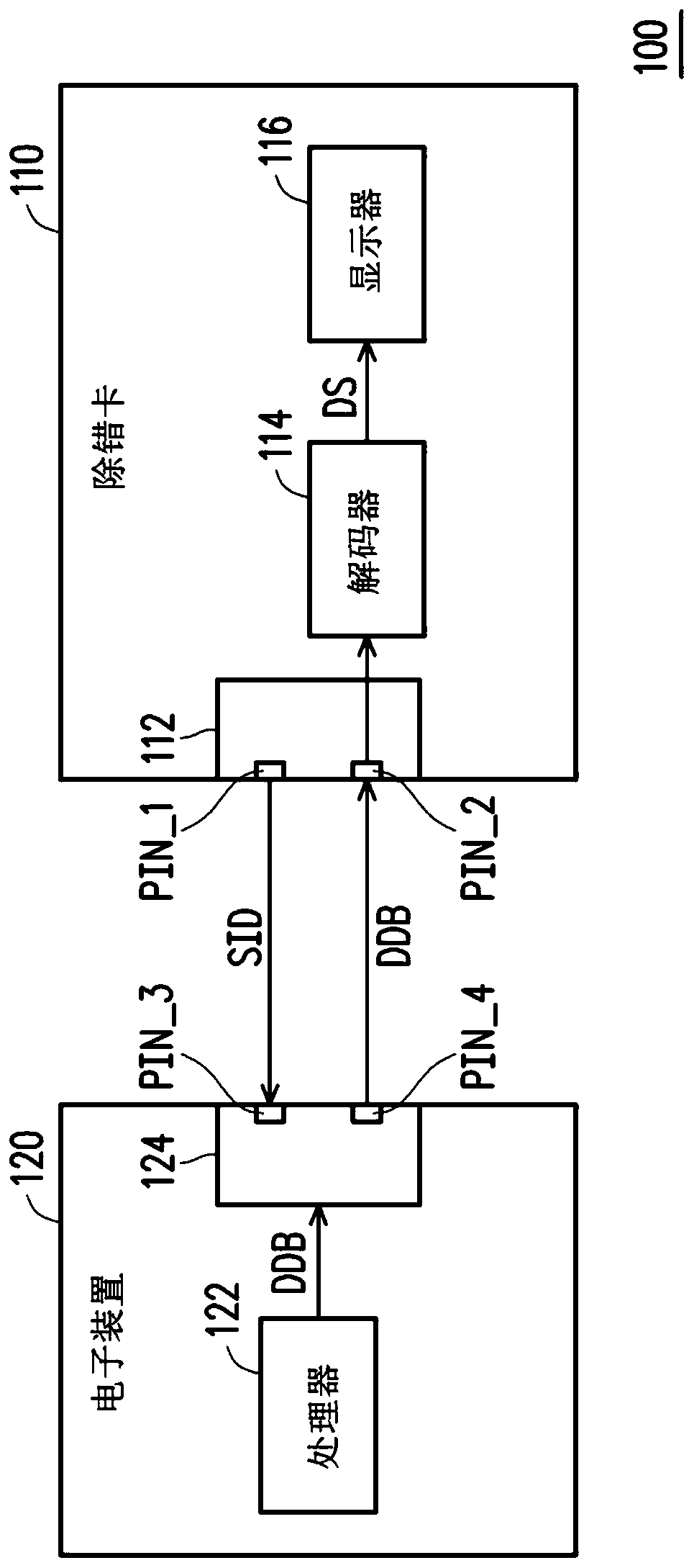
[0034] Please refer to figure 1 , figure 1 It is a schematic diagram of a debugging system according to an embodiment of the present invention. In this embodiment, the debugging system 100 includes a debugging card 110 and an electronic device 120 . The electronic device 120 can be, for example, a desktop computer, a notebook computer or a server. The debug card 110 can be detachably assembled with the electronic device 120 to obtain a debug code DDB, and display a debug result corresponding to the debug code DDB. In this embodiment, the debug card 110 includes a first connection port 112 . The first connection port 112 has at least a first pin PIN_1 and a second pin PIN_2 . The first pin PIN_1 is applied with the identification signal SID having a first logic level. In this embodiment, the first logic level is a high logic level (the present invention is not limited thereto). Therefore, the logic level of the first pin PIN_1 is maintained at a high logic level. The sec...


PUM


Abstract

A debug system is provided. The debug system includes a debug card and an electronic device. The debug card displays a debug result corresponding to a debug code. The debug card includes a first port.The first port has a first pin and a second pin. An identification signal having a first logic level is applied to the first pin. The electronic device includes a processor and a second port. The processor performs a debug operation to provide the debug code. The second port has a third pin and a fourth pin. When the second port is electrically connected to the first port, the third pin receivesthe identification signal and provides the debug code to the first port through the fourth pin according to the identification signal. The second pin receives the debug code.

Description

technical field [0001] The invention relates to a debugging system, in particular to a debugging system capable of knowing the debugging result without dismantling the electronic device. Background technique [0002] During the development and verification process of an electronic device (such as a desktop computer or a notebook computer), at least one debugging operation is performed to eliminate abnormal operation of the electronic device. However, the debugging results provided by the current debugging operation can only be obtained by disassembling the electronic device (for example, disassembling the casing of the electronic device). Therefore, the convenience of knowing the debugging result of the debugging operation must be improved. Contents of the invention [0003] The invention provides a debugging system capable of knowing the debugging result without dismantling the electronic device. [0004] The debugging system of the present invention includes a debuggin...

Claims


Application Information

Patent Timeline
Patent Type & Authority Applications(China)
IPC IPC(8): G06F11/07
CPCG06F11/0751H03K19/20G06F13/4282G06F11/273G06F11/2733H03K17/56G06F2213/0042
Inventor 陈中亮谢秉成
Owner COMPAL ELECTRONICS INC
Why Eureka
Try Eureka