
Passive filter parameter optimization method based on tunneling function

A technology of passive filter and optimization method, which is applied to harmonic reduction devices, AC networks to reduce harmonics/ripples, AC network circuits, etc., can solve cumbersome problems, increase design workload, etc., and achieve strong solving ability Effect

Active Publication Date: 2020-08-04
JIANGSU ELECTRIC POWER CO +1
View PDF6 Cites 0 Cited by
  • Summary
  • Abstract
  • Description
  • Claims
  • Application Information

AI Technical Summary

Problems solved by technology

The traditional industrial design method is relatively cumbersome. After the design of the filter capacity and parameters is completed, repeated verification is required to ensure the filtering effect and the stable operation of the system, but this greatly increases the workload of the design.

Method used


Image

  • Passive filter parameter optimization method based on tunneling function
  • Passive filter parameter optimization method based on tunneling function
  • Passive filter parameter optimization method based on tunneling function

Examples


Embodiment Construction

[0052] The specific implementation of the passive filter parameter optimization method based on the punching function of the present invention will be described in detail below in conjunction with the accompanying drawings.

[0053] Such as figure 1 As shown, it is the equivalent topology of the passive filter. The passive filter is composed of multiple sets of single-tuned filters (it is not limited to this combination method, and components can be added or removed according to specific project requirements, and this method is still applicable) .

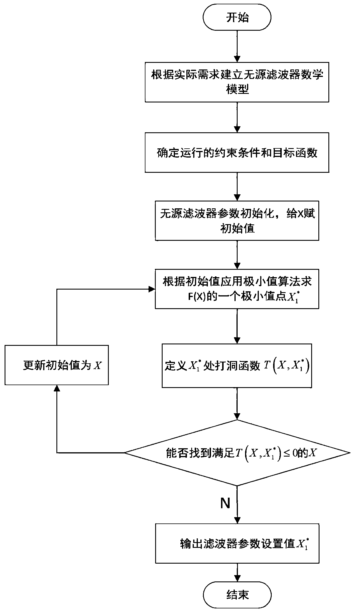
[0054] The flow chart of the passive filter parameter optimization method of the present invention is as follows figure 2 shown.

[0055] S1. Establish the mathematical model of the passive filter, determine the topology, functional model and component parameters that need to be set;

[0056] See attached Figure 1 , the main harmonics that the present invention plans to eliminate are 3, 5, 7, 11, 13, 17, and 19 harmonics resp...


PUM


Abstract

The invention discloses a passive filter parameter optimization method based on a tunneling function, and the method specifically comprises the following steps: (1), building a mathematic model of a passive filter, and determining a topological structure, a function model and element parameters needing to be set; (2), determining constraint conditions of operation of the passive filter; (3) determining a target and an optimization model of a passive filter optimization problem; (4), solving the optimization model of the passive filter by adopting a punching function; and (5), obtaining optimalelement parameters of the passive filter. The invention aims to provide a multi-harmonic and multi-period complex harmonic background passive filter parameter optimization method based on a tunnelingfunction algorithm, and the passive filter parameter optimization setting method takes harmonic control effect, investment cost and reactive influence on a system into consideration.

Description

technical field [0001] The invention relates to an optimization strategy applied to passive filter parameters, in particular to an optimization strategy based on multi-harmonic and multi-period complex harmonic backgrounds based on hole punching functions. Background technique [0002] The use of power electronics is a major factor in generating harmonics, which are generated when non-linear devices are present in the grid. Power electronic devices can be seen everywhere because of their wide application space, so the problem of harmonics in the power grid has always existed. [0003] The harm of harmonics cannot be ignored. Harmonic overvoltage can easily cause dielectric breakdown or reactive power overload, and in severe cases, it will cause power factor correction capacitors to fail. Harmonic overcurrent and voltage will cause the temperature of electrical equipment to overheat, resulting in degradation of insulation performance, thereby shortening the service life of ...

Claims


Application Information

Patent Timeline
Patent Type & Authority Applications(China)
IPC IPC(8): H02J3/01
CPCH02J3/01H02J2203/20Y02E40/40
Inventor 周宇王胜戴云峰周昕赵峰陈文冯兴明李正佳孙大军
Owner JIANGSU ELECTRIC POWER CO
Learn More