Orthopaedic sickbed convenient for patient to get out
A technology for patients and orthopedics, applied in the field of hospital beds, can solve problems such as inconvenient operation, and achieve the effect of easy getting out of bed and simple operation
- Summary
- Abstract
- Description
- Claims
- Application Information
AI Technical Summary
Problems solved by technology
Method used
Image

Examples
Embodiment 1
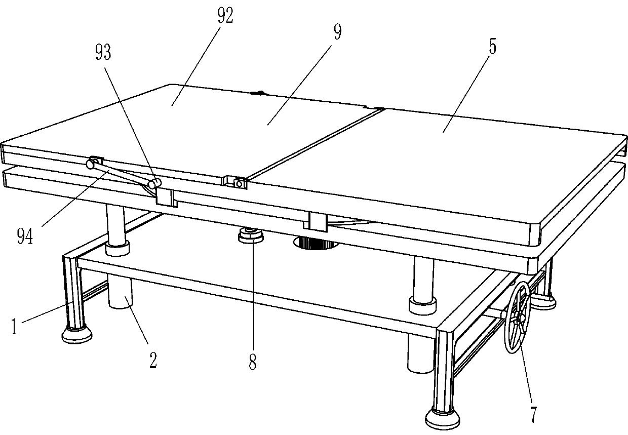
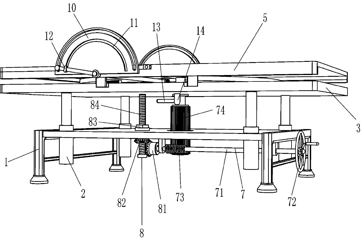
[0026] A hospital bed for orthopedics that is convenient for patients to get out of bed, such as figure 1 As shown, it includes a bed frame 1, a telescopic rod 2, a support plate 3, a fixed bed board 5 and a guide rail 6, and the left and right sides of the bed frame 1 are embedded with a telescopic rod 2, and the top of the telescopic rod 2 is connected with a support plate 3 , the left and right sides of the top of the support plate 3 are provided with guide grooves 4, and guide rails 6 are slidably connected to the guide grooves 4 on both sides. Mechanism 8, a rotating mechanism 7 is provided between the bed frame 1 and the fixed bed board 5, a lifting mechanism 8 is provided between the bed frame 1 and the support plate 3, and the lifting mechanism 8 is connected to the rotating mechanism 7 through transmission.
[0027] Rotating mechanism 7 comprises connecting shaft 71, handwheel 72, large worm screw 73 and large worm wheel 74, and bed frame 1 right part is connected wit...
Embodiment 2
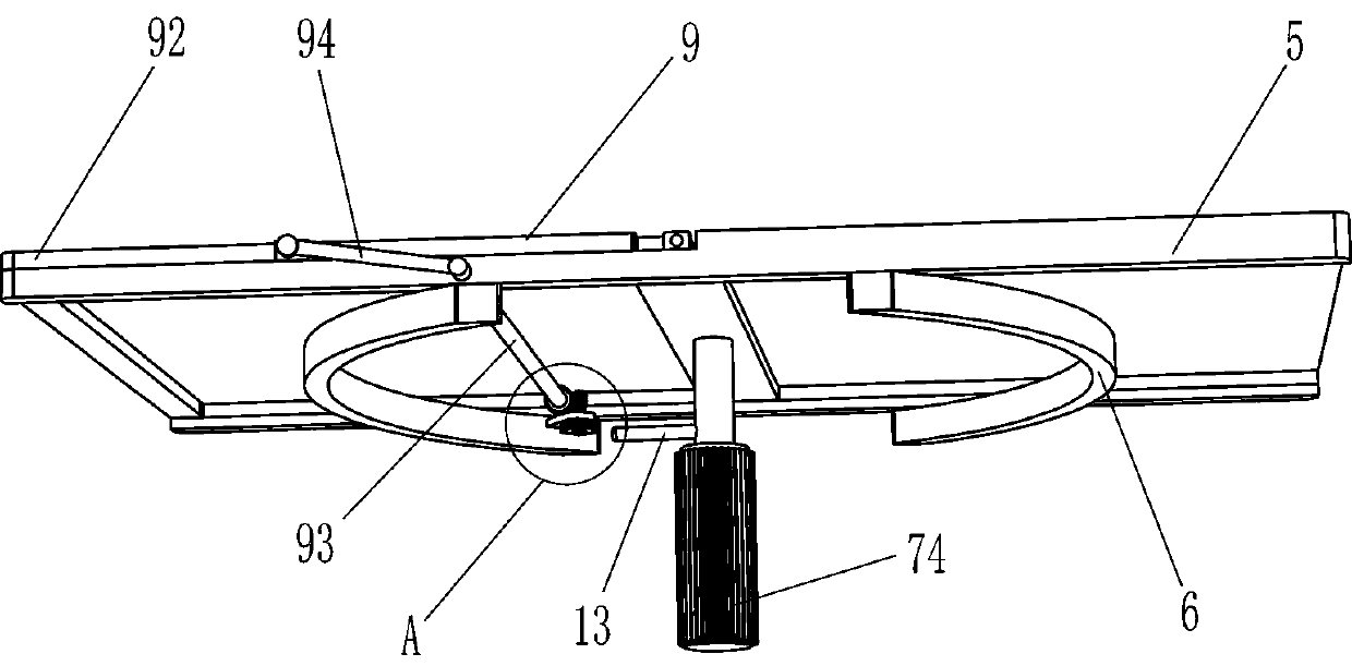
[0031] On the basis of Example 1, such as Figure 2-5 Shown, also include auxiliary mechanism 9 for getting up, and auxiliary mechanism 9 for getting up includes arc rack 91, movable back plate 92, rotating rod 93, connecting rod 94, rotating shaft 95, cylindrical gear 96, small worm screw 97 and small worm wheel 98 , the top left side of the support plate 3 is connected with an arc-shaped rack 91, the left side of the fixed bed plate 5 is hingedly connected with a movable back plate 92, and the left side of the fixed bed plate 5 is rotatably connected with a rotating rod 93, and the two ends of the rotating rod 93 are connected with Connecting rod 94, the ends of both connecting rods 94 are slidingly connected with the front and rear sides of the movable backing plate 92 respectively; The arc tooth bar 91 meshes, and the top of the rotating shaft 95 is connected with a small worm 97, and the rear side of the rotating rod 93 is connected with a small worm wheel 98, and the sma...
Embodiment 3
[0034] On the basis of Example 2, such as figure 1 Shown, also comprise fan-shaped plate 10 and slide block 12, all be connected with fan-shaped plate 10 on both sides of fixed bed board 5, have chute 11 on the fan-shaped plate 10, slide block 12 is connected in the chute 11 slidingly, slide The block 12 is connected with a connecting rod 94 which is slidingly fitted with the sector plate 10 .
[0035] When the connecting rod 94 rotates, it drives the slider 12 to rotate in the chute 11 , thereby playing a guiding role, and the connecting rod 94 rotates on the fan-shaped plate 10 when rotating, thereby supporting the connecting rod 94 .
[0036] Such as figure 1 As shown, also include fixed rod 13 and stop rod 14, be connected with fixed rod 13 on the large worm wheel 74, the bottom of support plate 3 is connected with limit rod 14, the included angle between stop rod 14 and fixed rod 13 is 9 Ten degrees.
[0037] The large worm wheel 74 also drives the fixed rod 13 to rota...
PUM
 Abstract
Description
Claims
Application Information
 - R&D
- Intellectual Property
- Life Sciences
- Materials
- Tech Scout
- Unparalleled Data Quality
- Higher Quality Content
- 60% Fewer Hallucinations
Browse by: Latest US Patents, China's latest patents, Technical Efficacy Thesaurus, Application Domain, Technology Topic, Popular Technical Reports.
© 2025 PatSnap. All rights reserved.Legal|Privacy policy|Modern Slavery Act Transparency Statement|Sitemap|About US| Contact US: help@patsnap.com