A building floor thickness detector

A technology of thickness detection and thickness measurement, which is applied in the field of construction, can solve the problems of measurement data error fluctuation, movement deviation, etc., and achieve the effect that it is not easy to deviate

Active Publication Date: 2021-09-03
江西润洋工程检测有限公司
View PDF0 Cites 0 Cited by
  • Summary
  • Abstract
  • Description
  • Claims
  • Application Information

AI Technical Summary

Problems solved by technology

[0005] In order to solve the above technical problems, the present invention provides a building floor thickness detector to solve the problem that the existing floor thickness gauge is also used in the detection of building acceptance. Placed on two opposite test surfaces of the floor, and when performing mobile sampling measurements, the transmitting probe and the receiving probe need to move in the desired direction at the same time, requiring two people to perform operational measurements, and because two people are moving It is prone to movement deviation, and then it is prone to the problem of error fluctuation of measurement data

Method used


Image

  • A building floor thickness detector
  • A building floor thickness detector
  • A building floor thickness detector

Examples


Embodiment 1

[0030] as attached figure 1 to attach Figure 5 Shown:

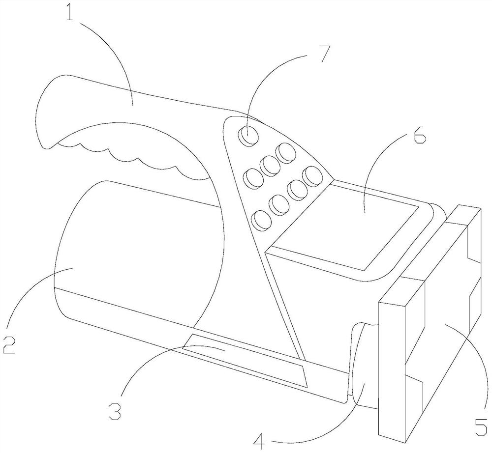
[0031] The invention provides a building floor thickness detector, the structure of which includes a handle 1, a power supply casing 2, a blockage bar 3, a receiving plate 4, a thickness measurement extension device 5, a display 6, and a control button 7. The handle 1 and the power supply The casing 2 is fixedly connected together, the blockage bar 3 is embedded and installed on the side of the power supply casing 2, the handle 1 is fixedly connected with the display 6, the receiving tray 4 is installed on the right side of the display 6, and the control The key 7 is embedded on the hand 1, and the receiving plate 4 is attached to the thickness measurement and abduction device 5 .

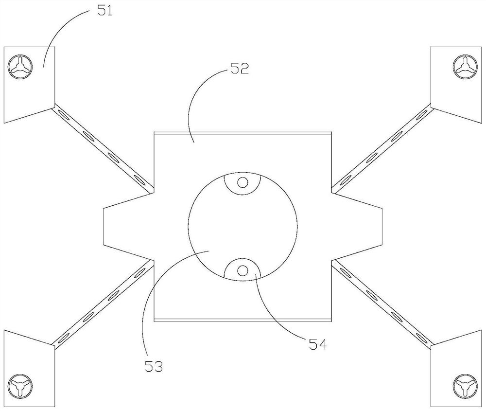
[0032] The thickness measurement outreach device 5 includes a spreading mechanism 51, a main sticking plate 52, a middle sticking plate 53, and a buckle piece 54. There are four spreading mechanisms 51 installed at the four corners of the ...

Embodiment 2

[0038] as attached Figure 6 to attach Figure 8 Shown:

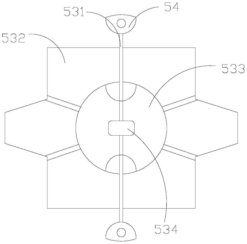
[0039] The present invention provides a building floor thickness detector. The extension mechanism 51 includes a clamping mechanism 511, a rotating disk 512, an inner rotating shaft 513, a display piece 514, and a stretching mechanism 515. The clamping mechanism 511 is embedded in the rotary On the disc 512, the inner rotating shaft 513 is installed on the rotating disc 512 by embedding, the spreading sheet 514 is fixedly connected with the inner rotating shaft 513, and the extending and pulling mechanism 515 is arranged on the right side of the spreading sheet 514 and fixed Installed on the surface, there are four extension mechanisms 51 that can be simultaneously deployed in four directions through the connection of the extension and pull mechanism 515, and are fixed by hooks to keep them in a stable state at the target point.

[0040] Wherein, the clamping mechanism 511 includes an elastic bar q1, a film q2, and a ...


PUM


Abstract

The invention provides a building floor thickness detector, the structure of which includes a handle, a power supply casing, a blockade strip, a receiving plate, a thickness measurement outreach device, a display, and a control button, the handle is fixedly connected with the power supply casing, and the blockade strip is embedded Installed on the side of the power supply casing, the handle is fixedly connected with the display, the receiving plate is installed on the right side of the display, the control button is embedded in the hand, and the receiving plate is fitted with the thickness measurement and extension device. During the working process of the present invention, The thickness measuring outreach device can be separated first, and the four extension mechanisms can be stretched toward the outside, and the middle sub-panel for receiving the connection line is fixed in the main sub-panel and used as the central measurement point at one end of the wallboard Expanding, the floor thickness gauge is used for detection at the other end, and only one person can accurately complete the thickness detection of the two opposite test surfaces of the floor through the transmitting probe and the receiving probe, and it is not easy to have deviations.

Description

technical field [0001] The invention belongs to the construction field, and more specifically relates to a building floor thickness detector. Background technique [0002] The floor thickness gauge can be measured without damaging the sample, and compared with the traditional measurement method, its measurement value is accurate and the error is small. An instrument for measuring the thickness of ferromagnetic media; when in use, place the transmitting probe and the receiving probe on two opposite test surfaces of the floor to transmit and receive electromagnetic fields respectively, and the instrument measures the thickness of the floor according to the received signal strength. [0003] Based on the above description, the inventors found that the existing building floor thickness detector mainly has the following deficiencies, such as: [0004] The floor thickness gauge is also used in the inspection of building acceptance, because when testing the wall, the transmitting ...

Claims


Application Information

Patent Timeline
Patent Type & Authority Patents(China)
IPC IPC(8): G01B15/02
CPCG01B15/02
Inventor 李成玉
Owner 江西润洋工程检测有限公司
Why Eureka
Try Eureka