Allocation of memory

A technology of memory allocation and memory, which is applied in the direction of memory architecture access/allocation, resource allocation, memory system, etc., and can solve problems that affect the performance of the processing system and conflicts

Active Publication Date: 2020-08-21
IMAGINATION TECH LTD
View PDF3 Cites 0 Cited by
  • Summary
  • Abstract
  • Description
  • Claims
  • Application Information

AI Technical Summary

Problems solved by technology

In this way, the processing system can simultaneously access different banks within the same memory (for example, read a register value from row 0 in bank 0 of memory, and read a register value from row 2 in bank 1 of memory), but Whenever simultaneous attempts are made to access the same group, a conflict occurs and one of the accesses must stop
This affects the performance of the processing system

Method used


Image

  • Allocation of memory
  • Allocation of memory
  • Allocation of memory

Examples


Embodiment Construction

[0042] The following description is presented by way of example to enable any person skilled in the art to make and use the invention. The invention is not limited to the embodiments described herein, and various modifications to the disclosed embodiments will be apparent to those skilled in the art.

[0043] Embodiments will now be described by way of example only.

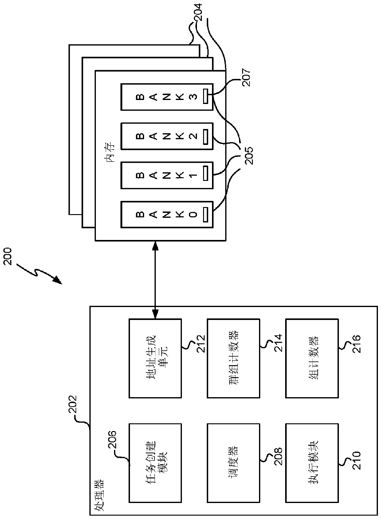
[0044] As described above, a processing system (eg, a system including a CPU or GPU and memory) may include multiple banks within memory. The executed instruction (eg, a read or write instruction) typically does not refer to any particular group, but only a register number, eg, read r0, where r0 refers to register 0. In known processing systems, an address generation unit maps register numbers to groups within memory based on a defined formula (or relation) such as:

[0045] (group number) = (register number) mod (number of groups)

[0046] (Equation 1)

[0047] And the address decoding logic within each grou...


PUM


Abstract

Methods of memory allocation are described. A first example method maps registers referenced by different groups of instances of the same task to individual logical memories. Other example methods described herein describe the mapping of registers referenced by a task to different banks within a single logical memory and in various examples this mapping may take into consideration which bank is likely to be the dominant bank for the particular task and the allocation for one or more other tasks.

Description

technical field Background technique [0001] In a processing system, when a task is created, a portion of memory is allocated to the task. The address generation unit then maps the registers referenced within the task to actual memory addresses within the allocated portion of memory. Two tasks can be assigned memory addresses within the same memory. Conflicts can occur when multiple access requests are made to memory at the same time. For example, two tasks can each request a value from memory, or a single task can request two values ​​from memory. This causes one access to have to stall until the other access completes. [0002] To increase read / write throughput (by reducing the occurrence of stalls), memory can be arranged into separate banks, and on any cycle, data can be read from each bank. In this way, the processing system can simultaneously access different banks within the same memory (for example, read a register value from row 0 in bank 0 of memory, and read a ...

Claims


Application Information

Patent Timeline
Patent Type & Authority Applications(China)
IPC IPC(8): G06F9/50
CPCG06F9/5016G06F12/0284G06F2212/1024G06F12/0223G06F2209/507G06F9/30123G06F9/3851G06F9/345G06F9/3885G06F3/0604G06F3/0659G06F3/0673G06F9/30101G06F9/324
Inventor 伊苏鲁·黑拉特R·布罗德赫斯特
Owner IMAGINATION TECH LTD
Why Eureka
Try Eureka