
Postoperative nursing drainage device for craniocerebral operation for neurosurgery department

A neurosurgery and craniocerebral technology, applied in suction containers, suction devices, hypodermic injection devices, etc., can solve the problems of reverse flow, not reminding medical staff, affecting the normal operation of the operation, etc., and achieve the effect of avoiding negligence and forgetting

Inactive Publication Date: 2020-08-25
CHANGZHOU NO 2 PEOPLES HOSPITAL
View PDF1 Cites 6 Cited by
  • Summary
  • Abstract
  • Description
  • Claims
  • Application Information

AI Technical Summary

Benefits of technology

This new method described in the current state-of-the art allows for better control over draining fluids during surgery without interrupting their flow or requiring manual interference. It also includes an improved mechanism called a blocker board which automatically opens up after use if needed while keeping other liquor containers closed properly. Overall, these improvements improve efficiency and accuracy in controlling bleeding during surgeries.

Problems solved by technology

This patented technical problem addressed in this patents relates to improving the safety and efficiency during neurosurgeries when draining fluids from necrotic areas caused by strokes or other accidents involving damage to blood vessels.

Method used


Image

  • Postoperative nursing drainage device for craniocerebral operation for neurosurgery department
  • Postoperative nursing drainage device for craniocerebral operation for neurosurgery department
  • Postoperative nursing drainage device for craniocerebral operation for neurosurgery department

Examples


Embodiment

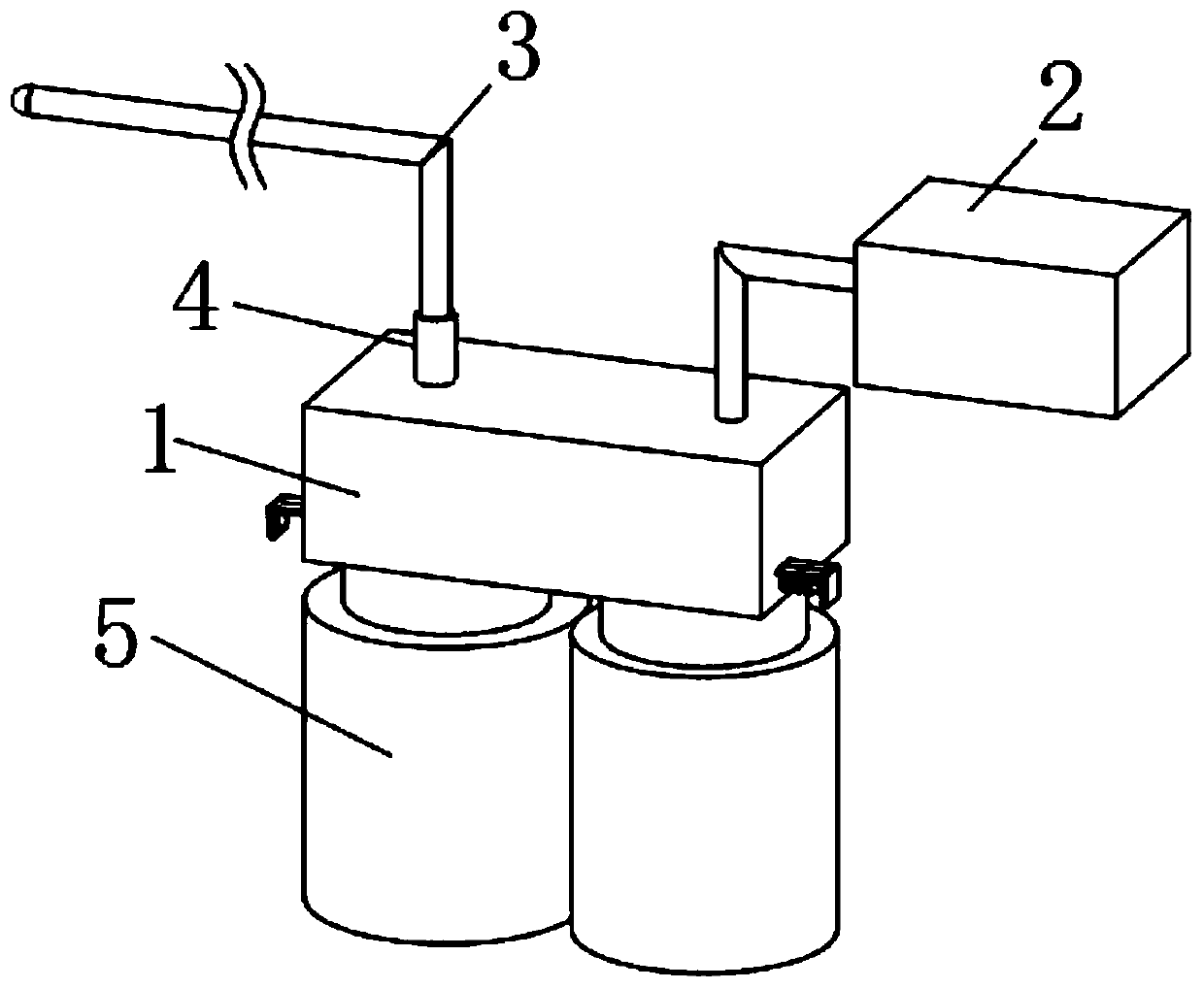
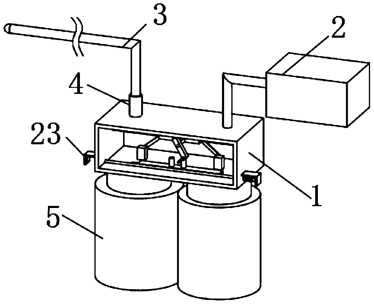
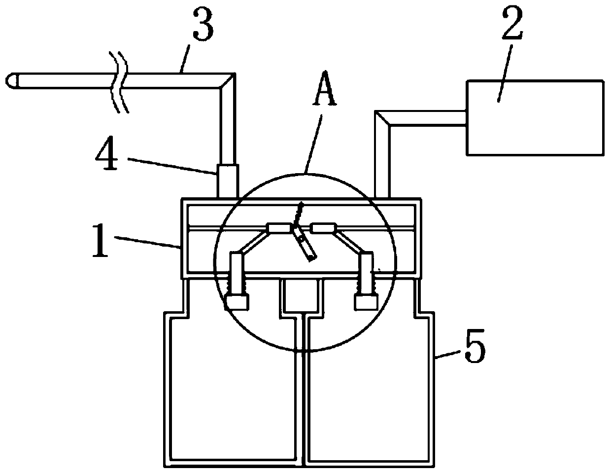
[0029] A kind of neurosurgical craniocerebral postoperative nursing drainage device of the present embodiment comprises a drainage box 1, an induced draft fan 2 is arranged above the drainage box 1, and the induced draft fan 2 communicates with the inside of the drainage box 1 through a connecting pipe, and the drainage box 1 Drainage tube 3 is provided on the top, and the drainage tube 3 is connected with the inside of the drainage box 1. The drainage tube 3 is provided with a one-way valve 4, and two liquid storage bottles 5 are fixedly installed under the drainage box 1. The bottom of the drainage box 1 Two liquid inlet holes 6 are opened on the side inner wall, and the two liquid inlet holes 6 correspond to the positions of the two liquid storage bottles 5 respectively. On the inner wall of one side of the drainage box 1, a rotating rod 7 is fixedly installed, and on the rotating rod 7 There is a rotating column 8 connected to the rotating sleeve, and the rotating column 8 ...


PUM


Abstract

The invention relates to the technical field of medical instruments, in particular to a postoperative nursing drainage device for craniocerebral operation for neurosurgery department. The device comprises a drainage box, and an induced draft fan is arranged above the drainage box and communicated with the interior of the drainage box through a connecting pipe. When the device needs to be used, theinduced draft fan is started, the induced draft fan generates negative pressure to drain a drainage liquid, the drainage liquid enters the drainage box along a drainage tube, and then enters a liquidstorage bottle on the left side through a liquid inlet hole in the left side; when the liquid storage bottle on the left side is full, a blocking plate can move leftwards, the liquid inlet hole in the left side is closed and a liquid inlet hole in the right side is opened, and the drainage liquid enters a liquid storage bottle on the right side through the liquid inlet hole in the left side; andsimilarly, after the right-side liquid storage bottle is full, the blocking plate moves rightwards and can switch to the left-side liquid storage bottle, drainage does not need to be stopped, normal operation of an operation is guaranteed, and when the liquid storage bottle is full, a bell rings to remind in time, so that forgetting caused by negligence of medical staff is avoided.

Description


Claims


Application Information

Patent Timeline
Owner CHANGZHOU NO 2 PEOPLES HOSPITAL
Learn More