Ball throwing device

A ball-throwing device and hemispherical technology, which can be used in animal taming devices, rackets, throwing equipment, etc., can solve the problems of inconvenient transportation and difficult control of long lever arms

Active Publication Date: 2020-10-09
PETSMART HOME OFFICE INC
View PDF4 Cites 0 Cited by
  • Summary
  • Abstract
  • Description
  • Claims
  • Application Information

AI Technical Summary

Problems solved by technology

Therefore, in order for users to achieve greater throwing distance, they may need to purchase a throwing device with a long lever arm, which is inconvenient to transport and more difficult to control

Method used


Image

  • Ball throwing device
  • Ball throwing device
  • Ball throwing device

Examples


Embodiment Construction

[0018] The following description is done for the purpose of illustrating the general principles of the device and is not meant to limit the inventive concepts claimed in this document. Furthermore, certain features described in this document can be used in combination with other described features in each of the various possible combinations and permutations.

[0019] Unless otherwise explicitly defined in this document, all terms should be given the broadest interpretation possible, including the meaning implied from the specification and the meaning understood by those skilled in the art and / or as defined in dictionaries, monographs, etc.

[0020] It must also be noted that, as used in the specification and appended claims, the singular forms "a", "an" and "the" include plural referents unless stated otherwise. Unless defined otherwise, all technical and scientific terms used herein have the same meaning as commonly understood by one of ordinary skill in the art. All public...


PUM


Abstract

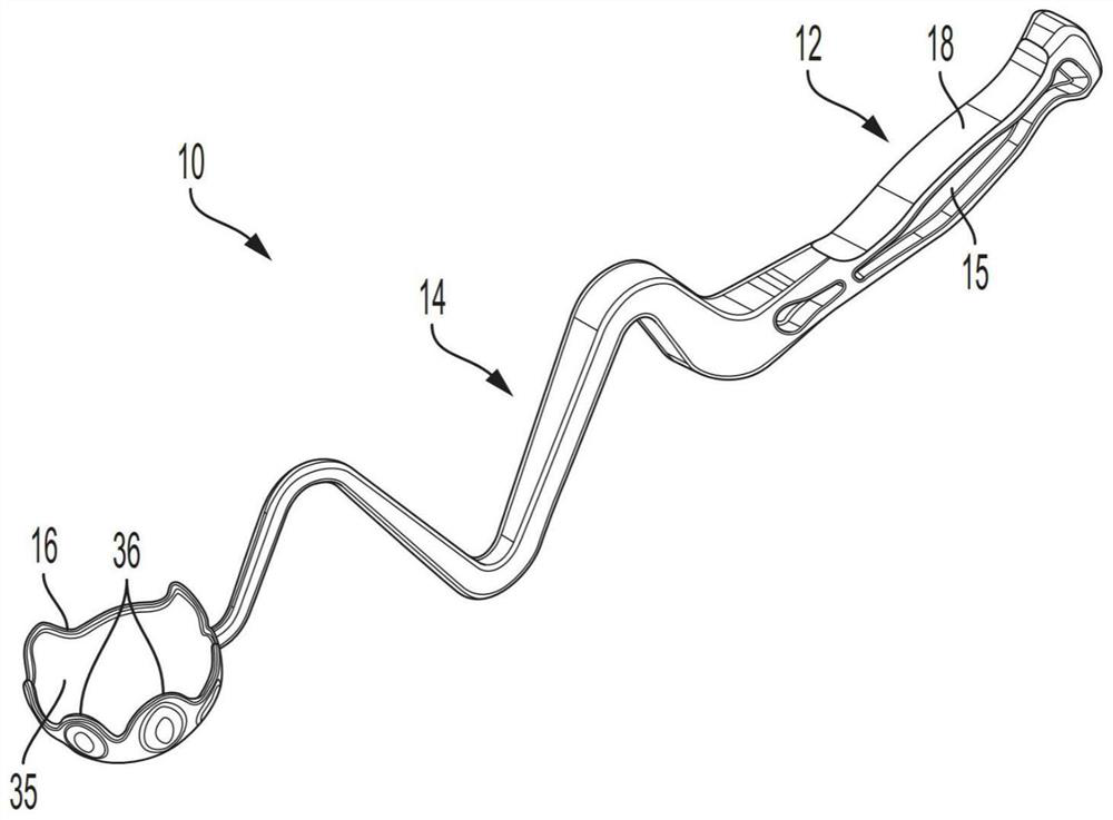
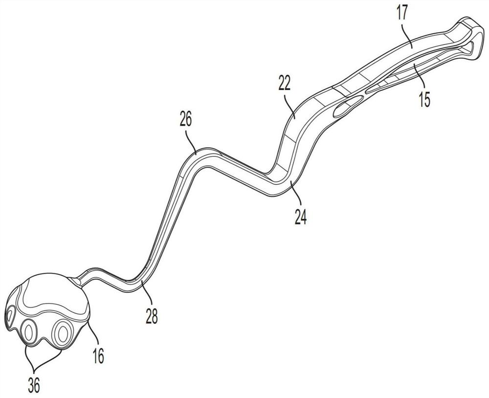
A ball throwing device includes a lower handle part, a middle lever part, and a head part. The middle lever part may include a plurality of latitudinal bends positioned between the lower handle part and the head part. Additionally and / or alternatively, the head part may include a half-spherical cup configured to releasably retain a ball, the half-spherical cup having a plurality of edge lobes configured to flex over an outside diameter of the ball.

Description

[0001] Cross References to Related Applications [0002] This patent document claims priority to U.S. Provisional Patent Application No. 62 / 824469, filed March 27, 2019, the disclosure of which is incorporated by reference in its entirety. technical field [0003] The present disclosure relates generally to pitching devices and, more particularly, to ball pitching devices having a shaft with multiple lateral bends for increased strength, efficiency, and power. Background technique [0004] Pitching devices have long been used for playing with pets, sports training, and more. Many such throwing devices utilize an elongated, slightly curved lever arm with a handle portion at the proximal end and a ball attachment cup at the distal end. Due to the elongated nature of the lever arm, the throwing device becomes an extension of the user's own arm, enabling the user to throw the ball over greater distances and / or at higher speeds without increasing the speed or power of their norm...

Claims


Application Information

Patent Timeline
Patent Type & Authority Applications(China)
IPC IPC(8): A63B69/00A01K15/02
CPCA63B69/00A01K15/025A63B59/20A63B2208/14A63B2209/00A63B2209/14A63B60/0081A63B60/08A63B60/12A63B60/06A63B60/48A63B60/52A63B65/122
Inventor P.塔穆莱维茨
Owner PETSMART HOME OFFICE INC
Why Eureka
Try Eureka